Hardware Specification
2017 Microchip Technology Inc. DS50002596A-page 65
B.5 STANDARD COMMUNICATION HARDWARE
For standard debugger communication with a target (Section 2.2 “Debugger to
Target Communication”), use an adapter with the RJ-11 connector.
To use this type of communication with a header board, you may need a device-specific
Processor Pak, which includes an 8-pin connector header board that contains the
desired ICE/ICD device and a standard adapter board.
For more on available header boards, see the “Processor Extension Pak and Header
Specification” (DS51292).
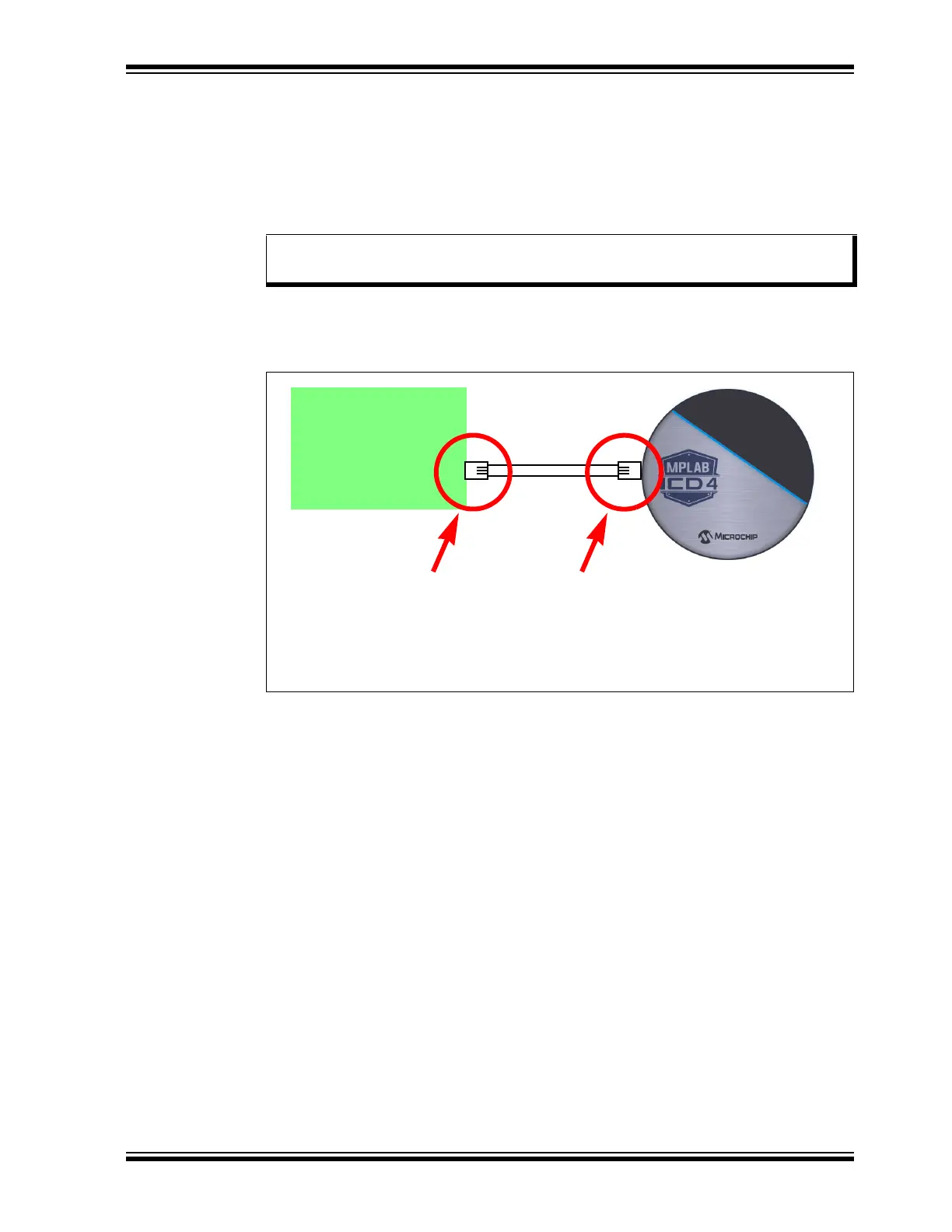
FIGURE B-1: COMMUNICATION CONNECTIONS
Note: Older header boards used a 6-pin (RJ-11) connector instead of an 8-pin
connector, so these headers may be connected directly to the debugger.
Target
For information on connecting the RJ-11
type cable to the RJ-45 Socket, refer to
Section B.5.1 “Connecting an RJ-11
Type Cable to an RJ-45 Socket on
MPLAB ICD 4 In-Circuit Debugger”.
For information on connecting
the RJ-11 type cable to the
target, refer to
Section B.5.2 “Standard
Communication”.