MPLAB
®
ICD 4 User’s Guide
DS50002596A-page 66 2017 Microchip Technology Inc.
B.5.1 Connecting an RJ-11 Type Cable to an RJ-45 Socket on MPLAB
ICD 4 In-Circuit Debugger
The MPLAB ICD 4 In-Circuit Debugger has an RJ-45 connector for communication to
the target. Connect the RJ-11 type cable into the RJ-45 connector by simply inserting
it into the center of the RJ-45 connector.
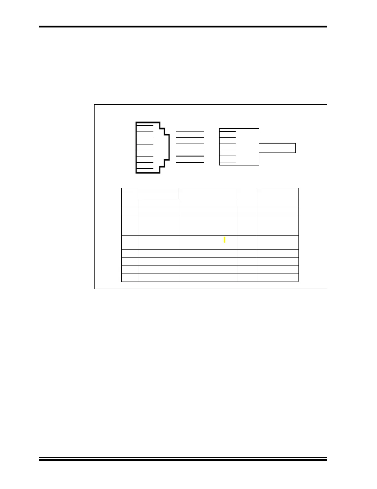
Refer to Figure B-2 for the pinouts for this connection.
FIGURE B-2: RJ-45 SOCKET TO RJ-11 CONNECTOR PINOUT
B.5.2 Standard Communication
The main interface to the target processor is via standard communication. It contains
the connections to the high voltage (V
PP), VDD sense lines, and clock and data
connections that are required for programming and connecting with the target devices.
The V
PP high-voltage lines can produce a variable voltage that can swing from 0-14V
to satisfy the voltage requirements of the specific emulation processor.
The V
DD sense connection draws very little current from the target processor. The
actual power comes from the MPLAB ICD 4 In-Circuit Debugger system, as the V
DD
sense line is used as a reference only to track the target voltage. The V
DD connection
is isolated with an optical switch.
The clock and data connections are interfaces with the following characteristics:
• Clock and data signals are in high-impedance mode (even when no power is
applied to the MPLAB ICD 4 In-Circuit Debugger system)
• Clock and data signals are protected from high voltages caused by faulty target
systems, or improper connections
• Clock and data signals are protected from high current caused from electrical
shorts in faulty target systems
RJ-45 Socket
1 2 3 4 5 6 7 8
1 2 3 4 5 6
RJ-11 Connector/Cable
Pin RJ-45 Function Pin RJ-11
1 TMS JTAG Test Mode Select
2 Reserved
3 PGC (ICSPCLK) Standard Com
Clock/TCK (JTAG Test
Clock)
2 PGC (ICSPCLK)
4PGD (ICSPDAT)
Standard Com Data/TDI
(JTAG Test Data Input)
3 PGD (ICSPDAT)
5 GND Ground 4 GND
6V
DD_TGT Power on target 5 VDD_TGT
7V
PP Power 6 VPP
8 TDO JTAG Test Data Output