Troubleshooting First Steps
2017 Microchip Technology Inc. DS50002596A-page 39
4.4 OTHER THINGS TO CONSIDER
1. Use the ICD Test Interface module to verify that the debugger is functioning
correctly (Section B.6 “ICD Test Interface Module”).
2. There may be a problem programming in general. As a test, switch to Run mode
(Run>Run Project
) and program the target with the simplest application possible
(e.g., a program to blink an LED). If the program will not run, then you know that
something is wrong with the target setup.
3. It is possible that the target device has been damaged in some way (e.g., over
current). Development environments are notoriously hostile to components.
Consider trying another target device.
4. Review debugger operation to ensure proper application setup. For more
information, see Chapter 2. “Operation”.
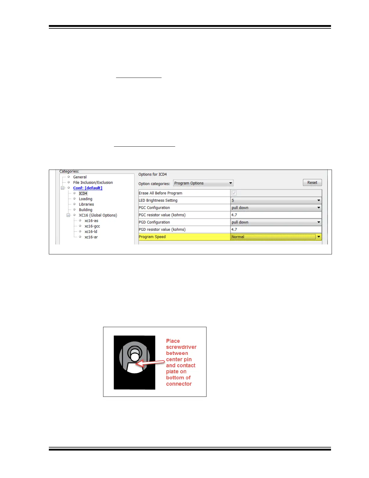
5. Your program speed may be set too high for your circuit. In MPLAB X IDE, go to
File>Project Properties
, Program Options, Program Speed and select a slower
speed from the drop-down menu. The default is Normal.
FIGURE 4-1: PROGRAM SPEED OPTION
6. If the MPLAB X IDE or MPLAB IPE cannot communicate with the MPLAB ICD 4
debugger (LEDs continually alternate between purple and blue), perform the fol-
lowing steps to force the debugger into Boatload mode:
a) Disconnect the Mini-B USB cable from the debugger.
b) Perform one of the following two options:
- If the recommended Microchip 9V power supply (AC002014) is
connected to the MPLAB ICD 4, unplug the power supply only from the
wall or power strip.
.
- If the recommended power supply is not being used, make sure no
power is connected to the debugger. Then, insert a small metal
screwdriver into the 9V female barrel connector so that it contacts the
center pin and the metal tang at the bottom of the jack.