MPLAB
®
ICD 4 User’s Guide
DS50002596A-page 20 2017 Microchip Technology Inc.
2.3 TARGET COMMUNICATION CONNECTIONS
2.3.1 Standard Communication Target Connection
Using the RJ-11 connector, the MPLAB ICD 4 In-Circuit Debugger is connected to the
target device with the modular interface (six conductor) cable. The pin numbering for
the connector is shown from the bottom of the target PCB in Figure 2-3.
FIGURE 2-3: STANDARD CONNECTION AT TARGET
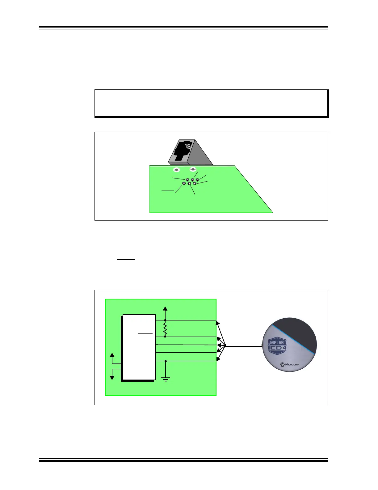
2.3.2 Target Connection Circuitry
Figure 2-4 shows the interconnections of the MPLAB ICD 4 In-Circuit Debugger to the
connector on the target board. The diagram also shows the wiring from the connector
to a device on the target PCB. A pull-up resistor (usually around 50 k) connected from
the V
PP/MCLR line to the VDD is recommended so that the line may be strobed low to
reset the device.
FIGURE 2-4: STANDARD CONNECTION TARGET CIRCUITRY
Note: Cable connections on the debugger and target are mirror images of each
other, i.e., pin 1 on one end of the cable is connected to pin 6 on the other
end of the cable. See Section B.5.3.3 “Modular Cable Specification”.
1
2
3
4
5
6
Target
Connector
Target
Bottom Side
PC Board
VPP/MCLR
Vss
PGC
V
DD
PGD
Reserved
VDD
VPP/MCLR
PGC
PGD
V
SS
AVDD
AVSS
2
1
5
4
3
User Reset
50K
Interface
Connector
Application
PCB
Device