Hardware Specification
2017 Microchip Technology Inc. DS50002596A-page 67
FIGURE B-3: 6-PIN STANDARD PINOUT
B.5.3 Modular Cable and Connector
For standard communication, a modular cable connects the debugger and the target
application. The specifications for this cable and its connectors are listed below.
B.5.3.1 MODULAR CONNECTOR SPECIFICATION
• Manufacturer, Part Number – AMP Incorporated, 555165-1
• Distributor, Part Number – Digi-Key, A9031ND
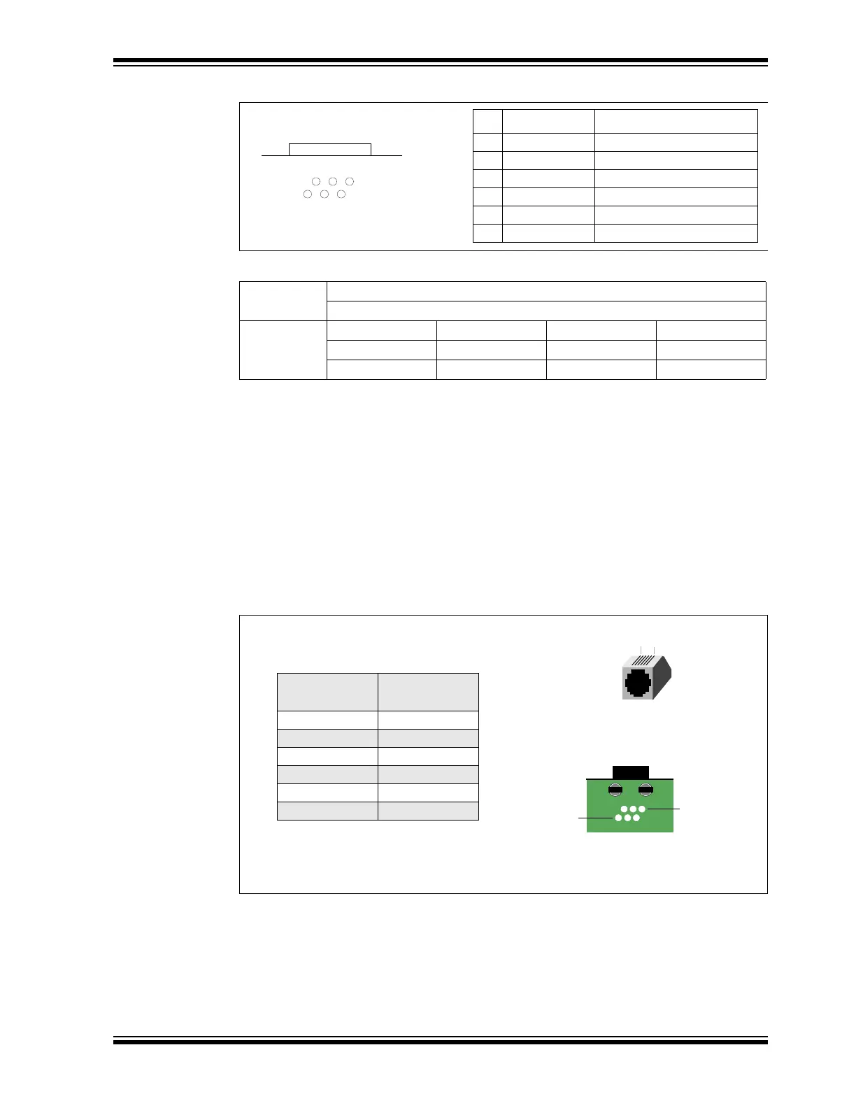
The following table shows how the modular connector pins for an application
correspond to the microcontroller pins. This configuration provides full in-circuit
debugger functionality.
FIGURE B-4: MODULAR CONNECTOR PINOUT OF TARGET BOARD
B.5.3.2 MODULAR PLUG SPECIFICATION
• Manufacturer, Part Number – AMP Incorporated, 5-554710-3
• Distributor, Part Number – Digi-Key, A9117ND
TABLE B-2: ELECTRICAL LOGIC TABLE
Logic Inputs VIH = VDD x 0.7V (min.)
VIL = VDD x 0.3V (max.)
Logic Outputs V
DD = 5V VDD = 3V VDD = 2.3V VDD = 1.65V
V
OH = 3.8V min. VOH = 2.4V min. VOH = 1.9V min. VOH = 1.2V min.
VOL = 0.55V max. VOL = 0.55V max. VOL = 0.3V max. VOL = 0.45V max.
1
2
3
4
5
6
Pin Name Function
1V
PP Power
2V
DD_TGT Power on target
3 GND Ground
4 PGD (ICSPDAT) Standard Com Data
5 PGC (ICSPCLK) Standard Com Clock
6- Reserved
Bottom of
Standard Socket
Target Board
Modular
Connector Pin
Microcontroller
Pin
6 Reserved
5 RB6
4RB7
3 Ground
2V
DD Target
1 VPP
1
6
Bottom View of Modular Connector
Pinout on Target Board
16
Front View of Modular
Connector on Target Board