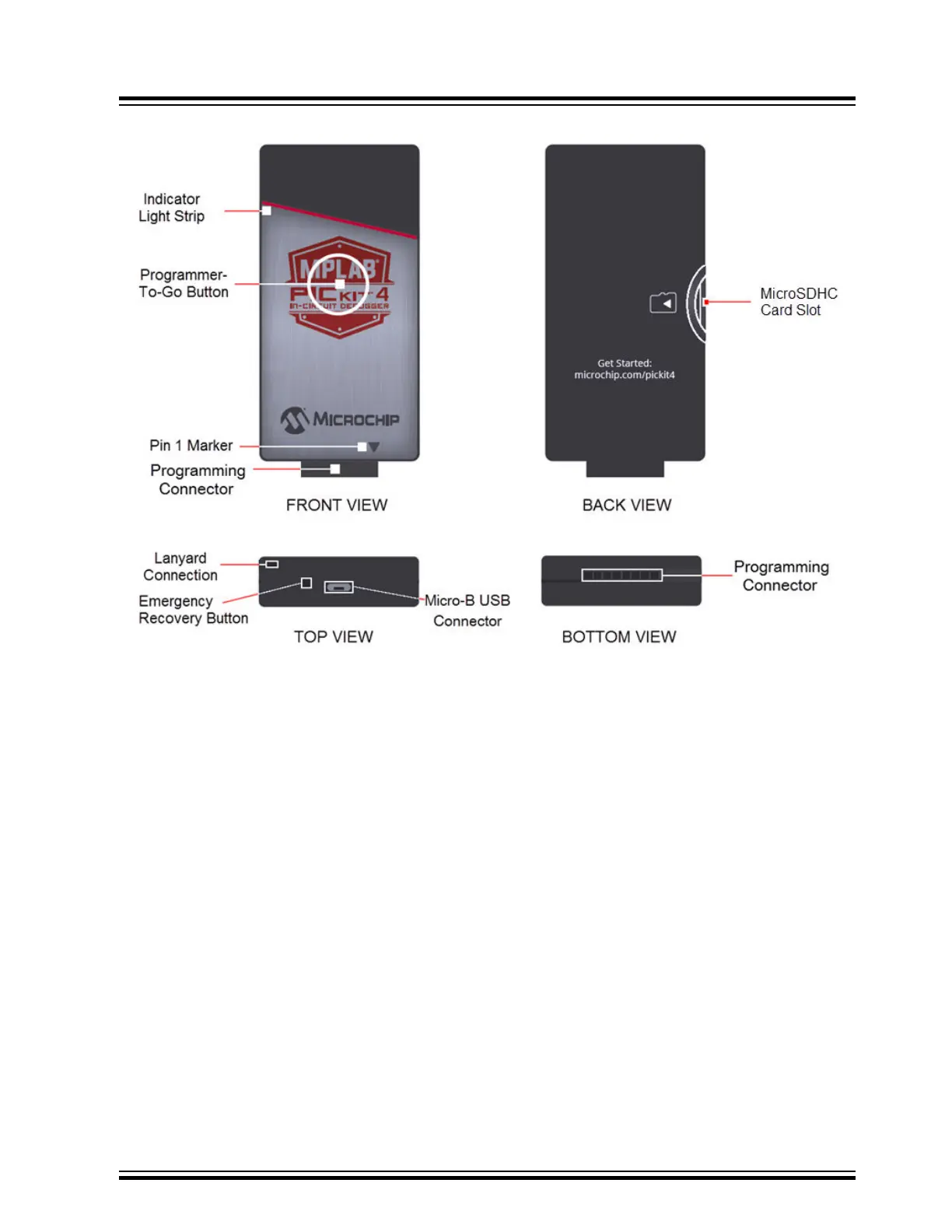
Figure 11-1. MPLAB
®
PICkit
™
4 In-Circuit Debugger
1. Lanyard Connection - An opening through the top and side for a lanyard (not included) to be attached.
2. Emergency Recovery Button - If needed, this recessed button is used for Recovery Boot Mode.
3. Micro-B USB Connector - Used to connect the debugger to the computer with the supplied USB cable.
4. Indicator Light Strip - Displays the operational modes of the debugger (see 11.2.2 Indicator Lights Strip).
5. Button Area - The area in the center of the shield logo is used for the Programmer-To-Go
1
option and for
invoking the bootloader mode (see 6.3.2 How to Invoke the Bootload Mode).
6. Pin 1 Marker - This designates the pin 1 location for proper connector alignment.
7. Programming Connector - The connector is an 8-pin SIL header (0.100" spacing) that connects to the target
device (see 11.3.2 Pinouts for Interfaces).
8. MicroSDHC Card Slot
1
- The microSDHC card slot supports a large variety of microSDHC cards with various
speed requirements.
Note:
1
The functionality will be available in a future firmware update of the product through MPLAB X IDE.
11.2.1 Main Board
The main board includes the following features:
• A 32-bit microcontroller using an Arm
®
Cortex
®
-M4 core.
• A USB 2.0 interface capable of USB speeds of 480 Mbps.
• An SRAM for holding the program code image. This image is used for programming on-board Flash device.
• One LED strip.
11.2.2 Indicator Lights Strip
The expected start-up sequence for the MPLAB PICkit 4 debugger is:
Hardware Specification
© 2020 Microchip Technology Inc.
User Guide
DS50002751D-page 57