3Flex Service Manual Upper Manifold Assembly
Aug 2013 2-7
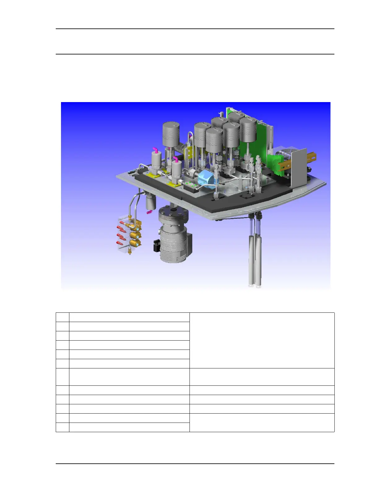
Upper Manifold Assembly
Shown below is a graphical representation of the upper manifold assembly. Refer to the table below
the graphic for component identification, as well as a link to additonal information for each componet.
This configuration may differ depending on whether the instrument has 1, 2, or 3 ports.
A 10-Torr manifold transducer See also Sample and Po Transducers
on page 2-10
B 0-1-Torr transducers
C 10-Torr transducers
D 1000-Torr manifold transducer
E Po port button-head transducer
F Sample ports button-head transducers
G Dual transducer PCBs See also Analysis Transducer Interface PCB, P/N:
350-17705-011
on page 2-20
H Heater assembly
I Gas inlets See also Gas Inlet Subsystem
on page 2-15
J Turbo pump See also Vacuum Subsystem
on page 2-13
K Po port See also Sample and Po Ports
on page 2-9
L Sample Ports