EasyManua.ls Logo

Micromeritics AccuPyc II 1340 User Manual

Micromeritics AccuPyc II 1340
158 pages
To Next Page IconTo Next Page
Page #1 background image
AccuPyc II 1340
Operators Manual
V1.09
134-42801-01
Oct 2013

Table of Contents

Questions and Answers:

Micromeritics AccuPyc II 1340 Specifications

General IconGeneral
ModelAccuPyc II 1340
Power Supply100 - 240 VAC, 50/60 Hz
Power Requirements100 W
Number of Cells1
Measurement PrincipleGas displacement
GasHelium
Volume Range0.01 cc to 350 cc
Sample SizeUp to 350 cm³ (depending on sample cell used)
Accuracy±0.1% of reading
Repeatability±0.01% of reading
Operating Temperature15°C to 35°C
Temperature Range15°C to 35°C

Summary

WARRANTY

1. GENERAL INFORMATION

Conventions and Symbols

Explains icons used for notes, cautions, and warnings in the manual.

Equipment Description

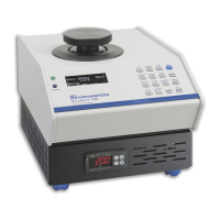
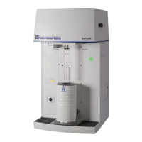
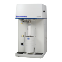
Details the AccuPyc II 1340 pycnometer's features, components, and operation.

Configurations and Options

Lists available sample chamber sizes, temperature control, and optional accessories.

MultiVolume Inserts

Details how to use inserts for analyzing smaller sample quantities.

Multigas Option

Explains the installation and use of the Multigas option for multiple gases.

2. INSTALLATION

Unpacking and Inspection

Guides on receiving, checking for damage, and returning the instrument.

Analyzer Installation

Instructions for locating, connecting, and setting up the pycnometer for operation.

Powering the Pycnometer

Procedures for safely turning the pycnometer on and off.

Handling System Components

Guidelines for handling calibration standards, sample chamber caps, and O-rings.

Specifying System Options

Details how to set language, units, date, and time defaults for the instrument.

Pycnometer Calibration

Step-by-step guide for calibrating the pycnometer to ensure accurate results.

Verifying Operation

Instructions for performing an analysis to confirm the instrument is functioning correctly.

Software Upgrades

Process for updating the pycnometer's software using USB media.

3. USER INTERFACE

Controls, Indicators, and Connectors

Describes front and rear panel controls, indicators, and connection ports.

Pycnometer Keypad

Explains the function and use of keypad keys and their combinations.

Pycnometer Display

Details the information displayed on the pycnometer's screen.

System Commands

Lists and explains available commands for operating the pycnometer.

4. GENERAL OPERATING INSTRUCTIONS

Preparing for Analysis

Steps for setting up the instrument and parameters before running an analysis.

Entering Analysis and Report Parameters

How to input analysis and report settings for optimal measurement outcomes.

Sample Preparation and Loading

Procedures for preparing samples and loading them into the instrument.

Starting an Analysis

Step-by-step guide to initiate and perform an analysis on the pycnometer.

Canceling an Analysis

How to stop an analysis that is currently in progress.

Viewing and Printing Data Results

Methods for accessing and printing analysis and calibration results.

Reviewing Data

How to review and potentially edit analysis or calibration results.

Using a Web Browser

Accessing analysis results via a web browser over the network.

5. TROUBLESHOOTING AND MAINTENANCE

Troubleshooting Common Problems

Identifies common operational problems and provides solutions.

Routine Maintenance

Details procedures for regular upkeep of the pycnometer.

Calibrating the Pycnometer

Instructions for checking and recalibrating the instrument for accuracy.

Chamber Cap O-Ring Maintenance

Guide for lubricating and replacing the chamber cap O-ring.

Checking for Leaks

Procedure to detect and diagnose leaks in the cell and expansion chambers.

Cleaning the Pycnometer

Instructions for cleaning the exterior casing of the instrument.

Cleaning the Dust Filter

Steps for cleaning the dust filter, specific to 2000-cm3 units.

Recovering from Power Failure

How the instrument handles and recovers from power interruptions.

6. ORDERING INFORMATION

Analyzer Equipment and Parts

Lists part numbers and descriptions for analyzer components and accessories.

Cables and Accessories

Part numbers for various cables, calibration kits, and gas accessories.

Sample Cups and Inserts

Lists part numbers for sample cups, inserts, and related components.

Software and Manuals

Part numbers for software, manuals, and keypad templates.

A. ERROR MESSAGES

Analysis and Calibration Error Codes

Details causes and actions for analysis (ANLSERR) and calibration (CAL_ERR) errors.

Data and Hardware Error Codes

Explains errors related to data processing (DATA_ERR) and hardware issues (HW_ERR).

Operational and User Error Codes

Covers errors during manual operations (MAN_ERR), power issues, and user input errors (USR_ERR).

Communication and Transmission Errors

Addresses issues with printer ports, data transmission, and network communication.

B. CALCULATIONS

Volume Calibration Calculations

Formulas for volume offset and volume scale calculations during calibration.

Analysis Calculation Formulas

Calculation formulas for sample volume and density based on unit size.

Run Precision and Sample Analysis Calculations

Explains calculations for run precision, pore volume, and solids concentration.

C. THEORY

Gas Displacement Theory for 10-, 100-, 350-cm3 Units

Explains the theoretical basis of gas displacement for specific unit sizes.

Gas Displacement Theory for 1-cm3 and 2000-cm3 Units

Explains the theoretical basis of gas displacement for other unit sizes.

D. TRANSMITTED DATA

Analysis Report Formats

Defines the format for analysis reports in single-column and spreadsheet.

Calibration Report Formats

Defines the format for calibration reports in single-column and spreadsheet.

E. MULTIPLE ANALYSIS MODULES

Connecting Modules to a Single Unit System

How to connect additional analysis modules to an existing single-unit system.

Connecting Modules to a Controller

How to connect analysis modules to a separate control module unit.

F. TEMPERATURE-CONTROLLED ACCUPYC

Attaching a Circulating Bath

Steps for connecting a circulating bath to the temperature-controlled unit.

Adding an Analysis Module

Procedure for adding an analysis module to a temperature-controlled unit.

G. SUPPORTED PRINTERS

Printer Compatibility Criteria

Lists criteria for printers to interface successfully with the analyzer.

H. RS-232 PIN ASSIGNMENT

I. KEYBOARD INTERFACE

J. MULTIVOLUME INSERTS

Operating Parameters for Inserts

How to enable the Chamber Insert prompt when using inserts.

Installing and Removing Inserts and Sample Cups

Guides for installing and removing various types of inserts and sample cups.

Calibrating Inserts

Steps for calibrating inserts to ensure accurate measurements.

K. MULTIGAS OPTION

Installing the Multigas Assembly

Steps for installing the valve assembly for the multigas option.

Connecting and Selecting Gases

How to connect gas supply tubing and select gases for analysis.

Related product manuals