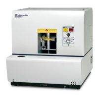
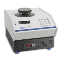
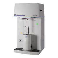
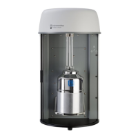
2 PRE-INSTALLATION INSTRUCTIONS
UNPACKING AND INSPECTION
When the equipment is received, unpack and inspect the contents of the shipping container(s).
Use the packing list to verify that all products, accessories, software (if applicable), and
documentation are received intact and in the correct quantity. The shipping container(s) and
contents should be inspected within a few days of receipt in the event damage or loss has
occurred. Sort through all packing material before declaring missing equipment or parts.
Micromeritics recommends saving all shipping containers until installation of the equip-
ment is complete. All shipping containers where equipment is to be declared as dam-
aged or lost must be examined by the claims investigator prior to completion of the
inspection report.
SHIPPING DAMAGE
If equipment is damaged or lost in transit, you are required to make note of the damage or loss on
the freight bill. The freight carrier, not Micromeritics, is responsible for all damage or loss occurring
during shipment. If damage or loss of equipment is discovered during shipment, report the
condition to the carrier immediately. Insurance claims MUST be made with the freight carrier, NOT
Micromeritics.
n Keep all software, manuals, and accessories with the equipment.
n Report any shipping damage immediately to the carrier and follow their directions.
n Report missing or wrong parts to Micromeritics, in addition to any shipping damage, only after
filing a claim with the carrier.
n Micromeritics will NOT file a claim for shipping damage.
n Do not discard shipping boxes and containers until installation is complete. If space is avail-
able, it is recommended that shipping containers be saved for future use in the event of return
to factory for repair.
2 Pre-installation Instructions
Flex Series Pre-installation Instructions and Checklist
350-42870-01 (Rev H) — Apr 2021
2 - 1
 Loading...
