3 Pre-installation Checklists
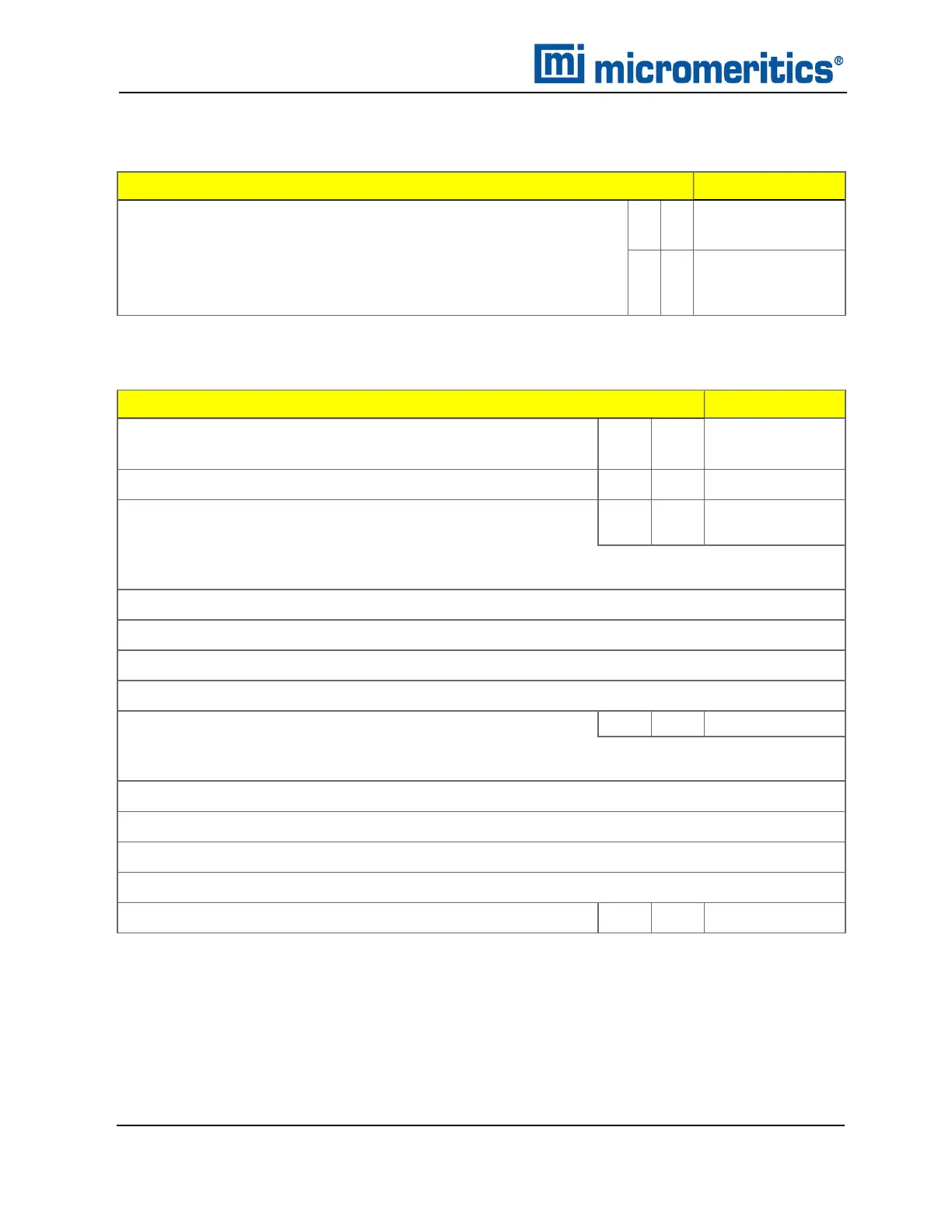
INSTALLATION CONFIGURATION CHECKLIST
Gas and Gas Supply Lines
Initial / Date
Will 1/8 in. copper gas supply lines (supplied with the analyzer for
standard installation) be used?
Y N
n If No, have 1/8 in. stainless steel gas supply lines been ordered
and received from Micromeritics?
Y N
ENVIRONMENTAL FACTORS CHECKLIST
Environmental Factors
Initial / Date
Is power available with the correct voltage and frequency, and
a safety earth ground?
Y N
Are temperature and humidity controlled within specifications? Y N
Are hazards present or precautions necessary in area of
installation?
Y N
n If Yes, please explain:
Are safety measures required? Y N
n If Yes, please explain:
For chemisorption units, are exhaust lines available?
Y N
3 - 2
Flex Series Pre-installation Instructions and Checklist
350-42870-01 (Rev H) — Apr 2021