D5CUB System Board Manual
Section 2: Configuring the D5CUB
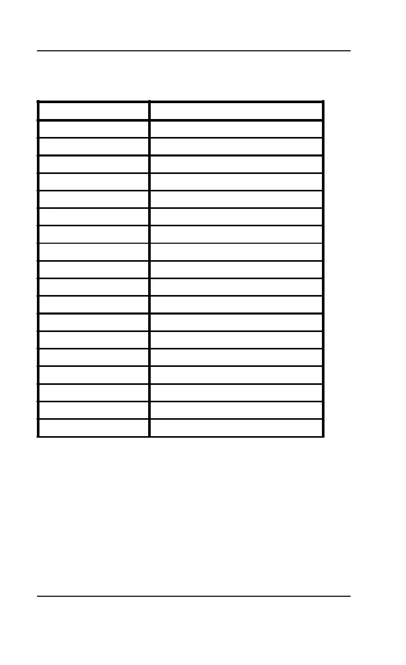
Table 2-12 lists all of the connectors and their functions.
20
Connector Number Function
J1 Keyboard connector
J2 PS2 Mouse connector
J3 External Battery connector
J4 Secondary IDE
J5 Primary IDE
J8 HDD LED
J10 Reserved
J11 Reset Switch connector
J13 Speaker connector
J15 Turbo LED connector
J16 Turbo Switch connector
J17 Power LED/Keylock connector
J18 Parallel Port (printer port) connector
J20 First Serial Port (COM1) connector
J21 Second Serial Port (COM2) connector
J22 Floppy Drive connector
J23 Reserved
J24 Reserved
Table 2-12: Connector Settings and Functions