D5CUB System Board Manual
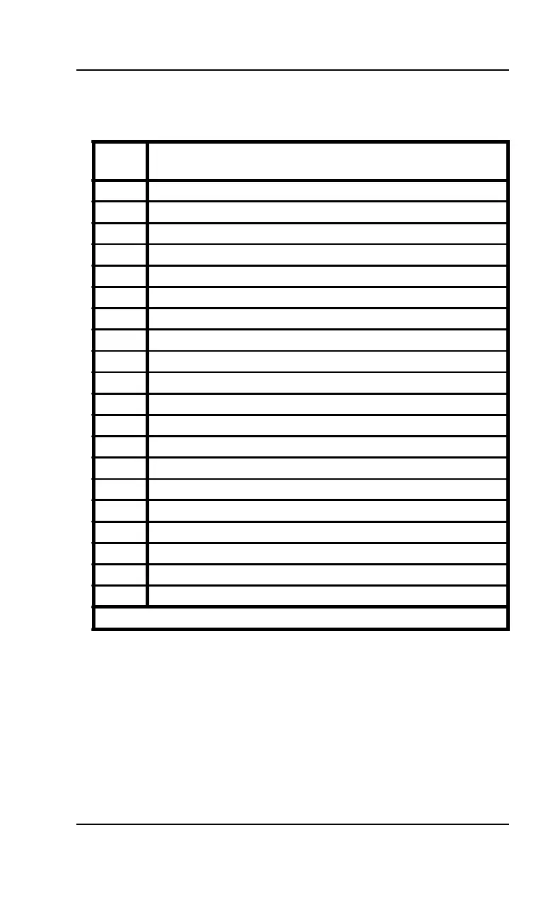
Table 2-11 lists all of the jumpers and their functions.
Section 2: Configuring the D5CUB
Jumper
Number
Function
JP1 TAG SRAM Type (See Table 2-5)
JP3 CPU Voltage Selection (3.3V*=1-2 STD; 3.4V=2-3 VR; 3.5V=4-5 VRE)
JP4 Multi I/O Chipset Enable/Disable (See Table 2-6)
JP5 System Speed Selection (See Tables 2-1 and 2-2)
JP6 System Speed Selection (See Tables 2-1 and 2-2)
JP7 Internal Cache Write-Through/Write-Back Selection (See Table 2-8)
JP8 Pentium CPU Type Selection (See Table 2-4)
JP9 Multi I/O Chipset Enable/Disable (See Table 2-6)
JP10 Reserved (Set to 3-5 and 4-6)
JP11 System Speed Selection (See Tables 2-1 and 2-2)
JP12 Color/Monochrome Selection (ON=Monochrome; OFF*=Color)
JP13 Clear CMOS Memory (ON=Clear; OFF*=Normal)
JP14 DRAM Refresh Rate (ON= 60MHz; OFF*=66MHz)
JP15 Clock Ratio (See Tables 2-4 and 2-9)
JP16 Clock Ratio (See Tables 2-4 and 2-9)
JP17 Reserved (Set to 2-3)
JP18 Sound Interface Enable/Disable (See Table 2-7)
JP19 Flash BIOS VCC Select (1-2=+12V; 2-3*=+5V)
JP21 EEPROM Size (2-3=2MB EEPROM; 1-2*=1MB EEPROM)
JP24 IRQ for PS/2 Mouse - Enable=ON* or Disable=OFF
* = Default setting
Table 2-11: Jumper Settings and Functions
19