in the 4-20mA mode listed in fi
3 Pair Termination:
Fully functional detector with continuous video and 4-20mA alarm output.
Reversal of polarity across terminals 1 & 2 will enable Micropack RS485
communication.
2 Pair Termination:
4-20mA output only with reversal of polarity across terminals 1 & 2
enabling Micropack RS485 communication.
3 Wire Termination:
4 Pair Termination:
Fully functional detector with continuous video, 4-20mA alarm output and
connected Micropack RS485 communication.
Micro
RS485 communication should
ersonnel.
Table 1: Current Level Out
with a tolerance of +/- 1mA
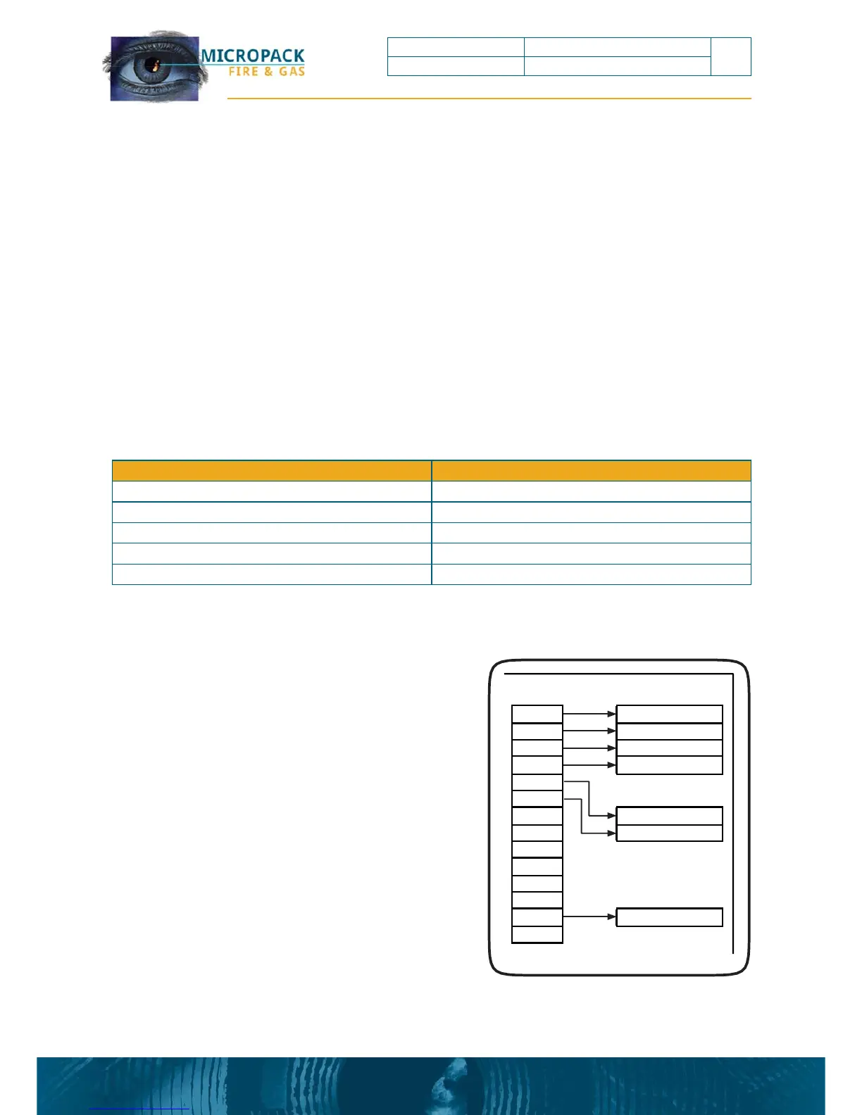
ure 9: 4 Pair Termination with rela
A further feature of the FDS301 flame detector
when configured in 4-20mA mode is that an
alarm relay is available if required. The alarm
relay contact closes on alarm and can be
employed by connecting to terminals 3 and 13 of
the device.
FDS301
Terminal
1
2
3
4
5
6
VideoOutput
RS 485
7
8
It is highly recommended to always connect
terminals 3 and 4 back to equipment room
marshalling cabinet with the use of a twisted pair
cable. This allow access to the RS485 from the
safe area.
9
10
11
12
13
14
micro
AlarmRelay
Video+
Video
‐‐‐
24Vdc
0Vdc
AlarmRela
Signal
Current Output Event
0mA Power/Detector Fault
2mA Optical Fault
5mA Healthy
18mA Alarm
21mA Over-range
FDS301 Flame Detector FDS301 Safety and Technical Manual
13
Ref: 2200.5009 Rev: 2.3 ECN 4434