DC Power
NOTE: Table 2 shows absolute maximums for cable lengths; try not to approach these values.
The overall performance and the transmission distance depend on the selected twisted pair
cable. Individually screened twisted pairs offer better electrical immunity.
It is not necessary for the DC power cable to be a twisted pair or individually screened, a 2-core
stranded cable with an overall screen is sufficient. The minimum conductor size is determined by
the cable length, the number of Flame Detectors on each loop and the maximum allowed voltage
drop at the last detector.
To prevent RS485 and Video common mode problems this is limited to a maximum of four volts
(4V) on the negative supply (0V).
micro
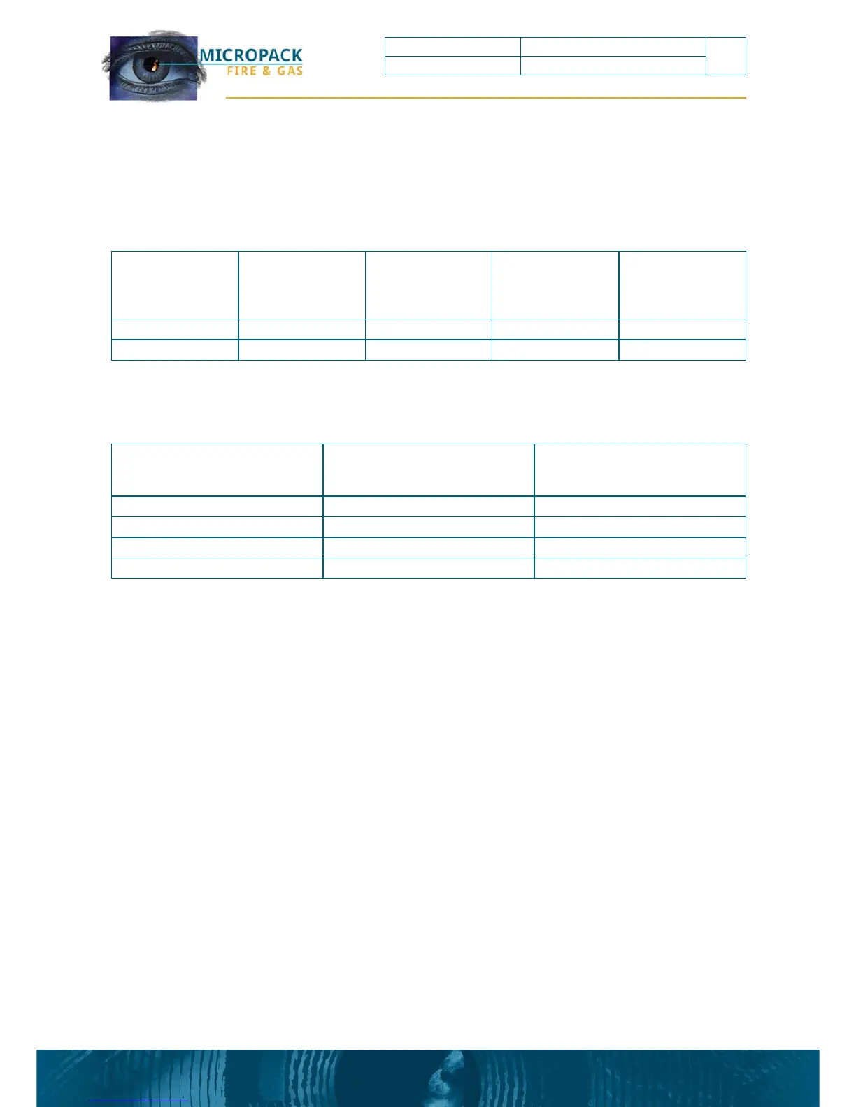
Cross Sectional Area (mm2)
American Wire Gauge (AWG)
Typical Conductor Resistance per
km (3280 ft.) DC Ohms /km @
20°C (approximate)
0.5 22 36
1 18 19
1.5 16 12
2.5 14 7.6
Installation based
on 24V nominal
supply
Number of Flame
Detectors
Maximum Power
(W)
Maximum Cable
Length (m) with
1.5mm2 Conductors
(12Ω/km)
Maximum Cable
Length (m)with
2.5mm2 Conductors
(7.6Ω/km)
Detector 1 6 1,000 1,578
Detector & Heater 1 15 480 800
FDS301 Flame Detector FDS301 Safety and Technical Manual
19
Ref: 2200.5009 Rev: 2.3 ECN 4434