3 Pair Termination:
Fully functional detector providing continuous video as well as alarm
and fault relays. Reversal of polarity across terminals 1 & 2 will enable
Micropack RS485 communication.
2 Pair Termination:
Alarm and Fault relay only with reversal of polarity across terminals 1 & 2
enabling Micropack RS485 communication.
4 Pair Termination:
Fully functional detector with continuous video, alarm and fault relays as
well as permanent Micropack RS485 communication connections.
Micro
RS485 communication should
ersonnel.
EOL and Alarm resistor values defined b
the client and the control s
are being integrated into.
3.4
Experience has shown that poor installation and commissioning practice may result in an
unreliable fire detection system that is prone to malfunction and unwanted alarms, and at
the same time fails to meet the site performance targets. Before installing the detector it is
important to take into account where it is to be located and how it is to be mounted.
3.41
Notes
When locating the detector consideration should be given to maintenance access to the detector.
The detector mounting should be secure and vibration free.
It is advisable to check the detection locations, prior to fabrication of the mounting supports, as
changes are frequently made during construction at site which can affect detector coverage.
The installation should allow subsequent space for detector removal, for maintenance or repair,
to be easily achieved.
1
The detector should be fixed to a stable supporting structure using the mounting bracket
provided. The supporting structure must allow for horizontal adjustment of the detector
orientation. The support structure should be in place prior to detector installation. Information
on mounting is available from Micropack (Engineering) Limited.
2
The threaded flame path of the enclosure cover and body must be protected from damage
during installation. Any such damage can destroy the validity of the enclosure.
3
The detector electronics shall be protected from mechanical damage and external sources of
EMI such as X-rays, RFI and electrostatic discharge. The detector should not face directly towards
the sun.
4
Fit the mounting bracket to the support structure using 8mm bolts (not provided). The detector
(bracket) should be oriented to provide the desired coverage.
5
The detector enclosure body should be fitted to the mounting bracket. The bolts locate into the
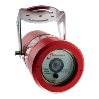
bracket. Twist the enclosure to locate the bolts; these are then tightened using a 6mm Allen key.
6 Ensure the detector is orientated such that the status led/earthing stud is directly beneath the lens.
7
Glanding should be carried out by trained personnel. The gland should be fitted in line with
installation standards for potentially explosive atmospheres that is 5 full threads minimum with
the IP seal washer fitted at the bottom of the thread This sealing arrangement will result in a
number of threads of the cable gland being visible. The gland should be torqued between 15 to
20 NM (11 to 15 lbf·ft).
FDS301 Flame Detector FDS301 Safety and Technical Manual
15
Ref: 2200.5009 Rev: 2.3 ECN 4434