The FDS301 design has been developed to allow simple installation. The detector comprises
two key components, the detector enclosure and the detector internal assembly. The detector
assembly located in the front of the enclosure should not be removed except by trained
personnel. Unauthorised removal or disassembly of the detector assembly will invalidate the
warranty. Only the rear end cap can be removed for terminal access.
3.1
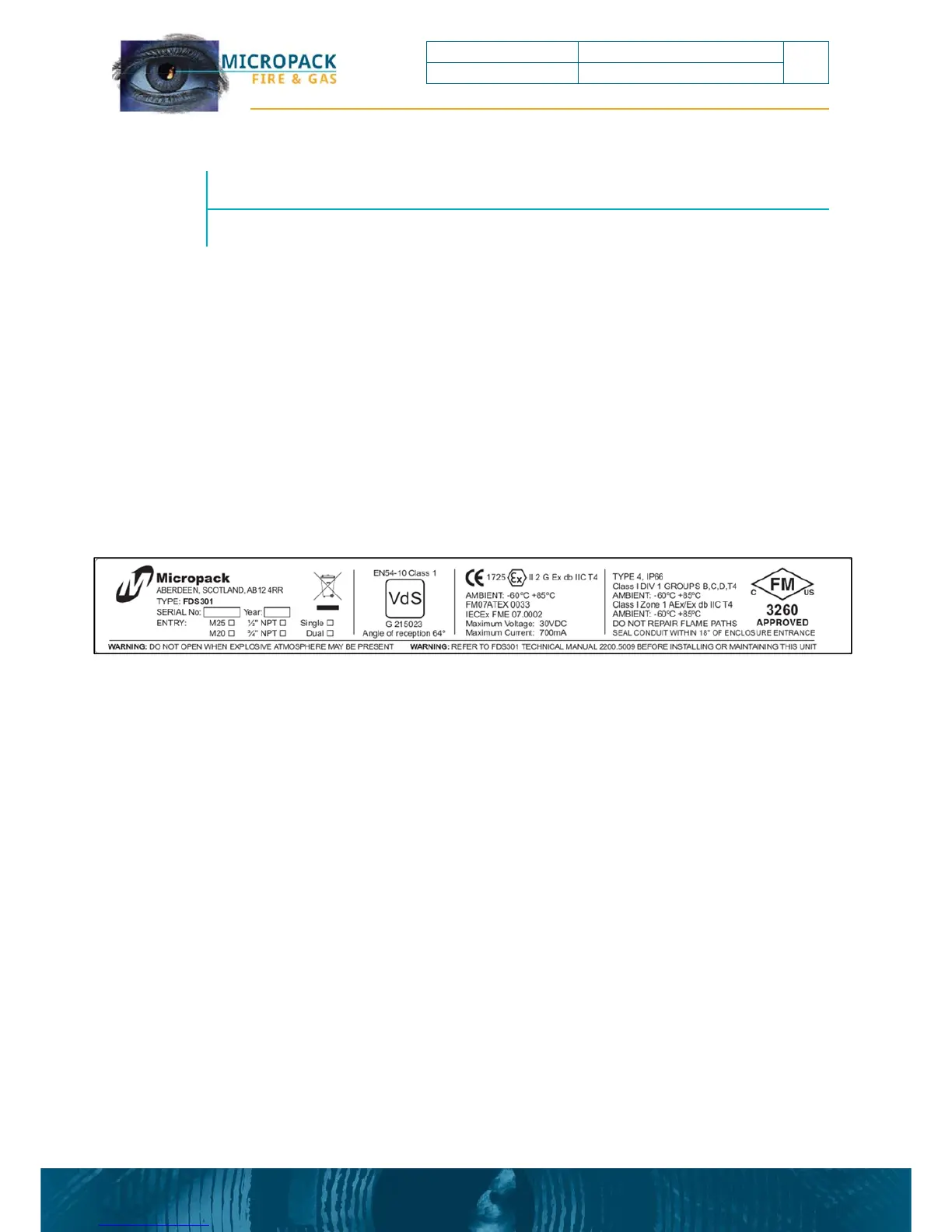
The detector electronics are housed in an enclosure certified for use in a hazardous areas. For
the exact certification and conditions of use see certification label on the device, or the example
drawing below:
The enclosure com
enclosure cover, the enclosure body (with certification label), and the mounting bracket.
This document is strictly private and confidential, reproduction without Micropack approval is prohibited. © Micropack Engineering Ltd, 2015
FDS301 Flame Detector FDS301 Safety and Technical Manual
8
Ref: 2200.5009 Rev: 2.3 ECN 4434