Caution
To prevent unwanted actuation or alarm, extinguishing devices must be inhibited/isolated prior
to performance testing or maintenance.
Caution
SIL 2 capability is only confirmed for 4-20mA output configuration of the FDS301 visual flame
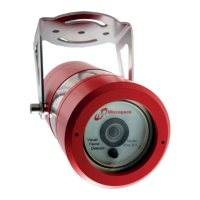
Detector Orientation
Detectors should be mounted with the earth stud/status led directl
below the lens to ensure the
90° horizontal field of view is achieved (see section 3.2 and 5.2 of this document).
Detector Positionin
Detectors should be positioned to provide the best unobstructed view of the area to be
protected. (see section 5.2 of this document).
The followin
factors should also be taken
Identify all high risk fire ignition sources. Ensure that enough detectors are used to
adequately cover the hazardous area.
Locate and position the detector so that the fire hazard(s) are within both the field of
view and detection range of the device.
For best performance, the detector should be mounted on a rigid surface in a low
vibration area. (see section 5.1 of this document).
Extremely dense fog or blizzard conditions could eventually block the vision of the
detector. (see section 5.4 of this document).
For indoor applications, if dense smoke is expected to accumulate at the onset of a fire,
mount the detector on a side wall (approximately 1 metre, 3 feet) down from the ceiling.
The FS301 flame simulator can be used to verify correct detector positioning and
coverage (see section 6.2 of this document).
The FDS301 has one sensitivity setting, this is factory set, and no changes can be made
to set-up except by fully trained Micropack engineers.
The detector carries out continuous internal hardware diagnostic testing to ensure
correct operation is relayed to the control system. It can also be set to indicate dirty
optics if this function is switched on. The detector should be subjected to a background
light level of at least 1 LUX in every 16 hour period for 1 hour.
The FDS301 is not designed to annunciate diagnostic failures of signal returns via
external wiring. Control systems and fire panels generally have fault monitoring for
such an eventuality.
•
FDS301 Flame Detector FDS301 Safety and Technical Manual
7
Ref: 2200.5009 Rev: 2.3 ECN 4434