In considering the application of the detector it is important to know of any conditions that may
revent the detector from res
within its field of view, and insensitivity to common false alarm sources. Solid obstructions or a
direct view of intense light sources may result in a reduction in the coverage and/or a reduction
in the detector sensitivity. Scaffolding or tarpaulins in the detector’s field of view may reduce
coverage. Contamination of the detector window may result in a reduction in sensitivity.
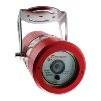
The detector provides a live colour video image for surveillance of the protected area. As with
conventional video cameras the detector should not face directly towards the sun or a brightly lit
scene. In such conditions the detectors automatic exposure control would darken the image in
order to avoid overexposure; the resulting picture may be too dark for surveillance purposes. In
the case of an offshore vessel or platform, the detector should ideally be placed facing inwards
towards the plant and with minimal view of the horizon.
The detector has a horizontal field of view of 90° and a vertical field of view of 65°. The location
and orientation of the detector in relation to the protected area determines the actual footprint.
Achieving the desired coverage depends on congestion within the protected space, the location
of the detector(s) and the distance of the detector from the hazard. It may be necessary to install
more than one detector within an area in order to achieve adequate coverage.
The detector sensitivity, expressed as fire size at a distance, is determined visually by the
apparent size of the fire. This is a function of the fuel source, how it is released and distance
from the detector to the fire. The detector response time is relatively independent of fuel t
and/or distance.
In common with other forms of flame detection the detector’s sensitivity is reduced and
potentially blinded by dense obscurants such as smoke, fog and other airborne particulates. The
detector is insensitive to arc welding, however this should not be conducted within 1m of the
detector.
5.1
The following guidelines have been based on operational feedback, reflecting commonly
experienced problems which can be traced to a failure to observe the following:
•
Ensure the mounting position is free from vibration or movement.
Prevent accidental knocking or forcing out of alignment.
To ensure the best possible video image the detector should be facing away from the sun.
Isolate as far as possible from local electrical interference sources.
Ensure sufficient detection to achieve adequate coverage for all likely hazards.
Minimise exposure to contamination of the detector face plate.
Ensure ease of maintenance access to detector (i.e. direct, ladder or scaffold access).
All these issues are of crucial importance to a successful installation and they should be afforded
great attention during the detailed design, construction and commissioning phases of the work.
This document is strictly private and confidential, reproduction without Micropack approval is prohibited. © Micropack Engineering Ltd, 2015
FDS301 Flame Detector FDS301 Safety and Technical Manual
21
Ref: 2200.5009 Rev: 2.3 ECN 4434