XYZ CHANNEL RECORDING (7 ELECTRODES)
ELECTRODES
This electrode configuration is suggested for:
― Derived 12 channel ambulatory recordings*.
― High Resolution 20min recordings for late potential analysis; for this application a
shielded cable is recommended to reduce noise level.
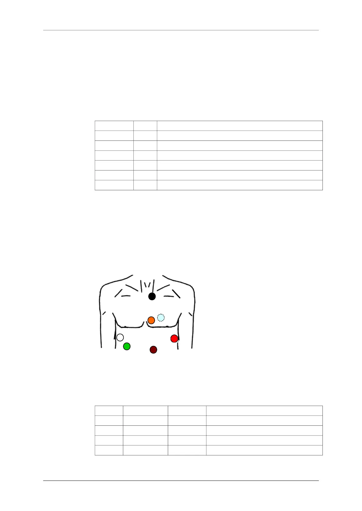
White X- Fourth intercostal space in right midaxillary line
Red X+ Fourth intercostal space in left midaxillary line
Black Y- Superior aspect of the manubrium
Brown Y+ Lower ribs
Blue Z- Directly posterior to V2
Orange Z+ Standard V2 position
Green ref Over 8th rib in right midclavicular line
Cable length: 152 cm
* Available with SyneScope Holter software.
ELECTRODE PLACEMENT
For an ambulatory orthogonal ECG recording close to the XYZ late potential configuration,
the following hook-up is recommended. However, due to constraints of daily activities, some
minor variations may be introduced, provided that polarity of electrodes and axis orientations
are maintained.
TWELVE-LEAD RECORDING* (10 ELECTRODES)
ELECTRODES
1 Yellow LA Left Anterior acromium
2 Red RA Right Anterior acromium
3 Green LL Left Interior iliac crest
10 Black GND Right Interior iliac crest
4 Purple V1 V1 position
8.4.
8.4.1.
8.4.2.
8.5.
8.5.1.
8. POSITIONING THE ELECTRODES
18 SpiderView – UA10709B