SH-HC30 Height Controller System Manual
Note: Those without pin number will not be used.
Table 3-5 The pin definition of J2 connector
No. Property Description
1 Power supply Ground
2 Input
Plasma arc voltage positive terminal (clip for connecting with
steel plate)
3 Input Plasma arc voltage negative terminal (arc voltage output)
Note: push the orange button inside and insert the stripped cable into the wiring hole and then release.
Table 3-6 The pin definition of J3 connector
No. Property Description
1 Power supply
~220V±10%
2 Power supply
~220V±10%
The voltage divider board may choose the installation position as required, but note: J1 interface is
low-voltage signal; J2 is the high-voltage signal. In order to prevent the interference of
high-pressure and high-frequency signals on the low-voltage signal and improve the stability of the
system, the wire laying of J1 and J2 should be carried out independently.
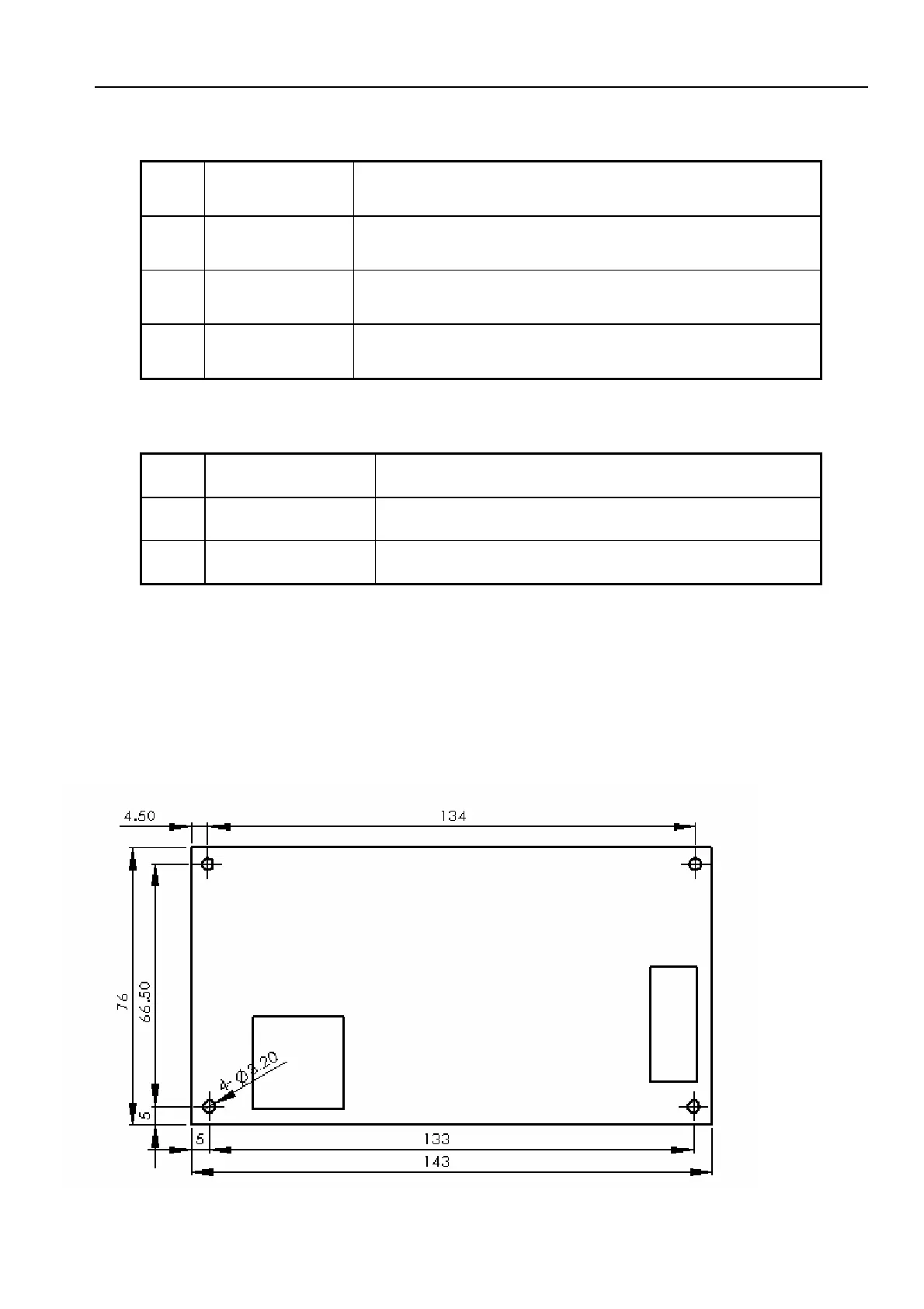
3.4 Dimensional drawing of voltage divider board
Page
16
 Loading...