SH-HC30 Height Controller System Manual
Page
22
When the capacitive height measurement is adopted, the specific inductive capacity (SIC) between the
capacitance detection ring and the cutting board may affect the height measurement accuracy due to the
temperature, pressure, humidity, gas composition and many other factors on site. In addition, the serious
non-linear relationship exists between the capacitance value and the height value. Our company has
developed the intelligent program of "a key height calibration ". On site you only need to press a key, you
can set various change factors automatically on site and realize the display and control of high accuracy, high
precision and high linearity within 3-30mm.
In the following situations, the height calibration is needed.
1. When the equipment is used for the first time;
2. When the use environment of equipment changes;
3. When you find that the actual height of capacitance detection ring is not consistent with its display height.
Because "a key height calibration" is very simple, you only need to press a key, the users may calibrate at
any time.
6.2 Debugging steps of a key height calibration
Check: the circular ring at the bottom of capacitance detection ring must be parallel to the cutting
board.
Turn on the cutting torch height controller.
Set the detector mode as the capacitance detector mode (for the method see 7.3).
In manual mode, the cutting nozzle is adjusted to be connected with the cutting board.
Press the key "down arrow" on the height control panel for about two seconds "; a key height
calibration” starts automatically, as follows:
1.Rise to about 30mm high in five steps;
2. And then fall to about 10mm from the cutting board and stop;
3. All the calibration is completed.
The initial debugging is finished.
For the height control operation see 5.2 and5.3.
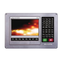
7. Controller Panel
There are display and keys on the height controller panel. Through the panel operation, you can modify
relevant parameters and monitor operation status.
7.1 Control Parameters
Set value (A: Accuracy Height): the expectation value of the space (height) between the cutting nozzle
and the cutting board, set by the user. For the set range and factory value see Table 7-1.
Dead zone value (E: Error Area): When the actual height is A ± E, the cutting torch height is not
adjusted any more (see 1.4). For the set range and factory value see Table 7-1
Speed regulating zone (d: Down Speed Area): the speed regulating zone is between AEd ~ AE, and A
+ E ~ A + E + d (see 1.4). For the set range and factory value see Table 7-1.
High limit place (H: High Limit): When the cutting torch position is higher than the set value, display
alarm, and moving-up stops. For the set range and factory value see Table 7-1.
Low limit place (L: Low Limit): When the cutting torch is lower than the set value, display alarm, and
moving-down stops. For the set range and factory value see Table 7-1.