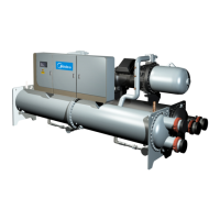
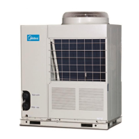
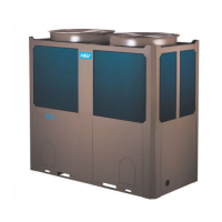
Flooded type water cooled screw chiller (PCB Control) MCAC-CTSM-2012-11
2
Contents
I. Product ......................................................................................................................... 3
1. Product Lineup ......................................................................................................................... 3
2. Nomenclature ........................................................................................................................... 3
3. Features .................................................................................................................................... 4
4. Operating Range ...................................................................................................................... 6
5. Specification ............................................................................................................................. 7
6. Performance Data .................................................................................................................... 9
7. System Schematic Diagram .................................................................................................. 14
8. Outline Dimension ................................................................................................................. 14
9. Water Flow .............................................................................................................................. 14
II. Installation .................................................................................................................. 15
1. Unit Lifting .............................................................................................................................. 16
2. Installation Location Select ................................................................................................... 14
3. Installation Foundation .......................................................................................................... 16
4. Vibration Isolators .................................................................................................................. 18
5. Installation of Water Pipeline System .................................................................................. 19
III. Electrical Data ............................................................................................................ 23
1. Field Wiring............................................................................................................................. 23
2. Electric parameter table ........................................................................................................ 26
3. Control Flow Chart ................................................................................................................. 27
4. Control Screen Structures .................................................................................................... 29
5. Control Screen Operation ..................................................................................................... 30
6. Introduction of Major Electric Components ......................................................................... 42
IV. Maintenance and Commissioning ............................................................................ 44
1. Commissioning ...................................................................................................................... 44
2. Maintenance and Service ...................................................................................................... 51
V. Control ........................................................................................................................ 79
1. Description of Energy Adjustment ....................................................................................... 79
2. Description of Cooling tower fan control ............................................................................. 81
3. Description of Oil heater control .......................................................................................... 81
4. Pump Control ......................................................................................................................... 83
5. Demand Limit ......................................................................................................................... 83
6. EXV operation & Wiring ......................................................................................................... 79
Appendix 1 ....................................................................................................................... 85
Appendix 2 ....................................................................................................................... 86
Appendix 3 ....................................................................................................................... 87
Appendix 4 ....................................................................................................................... 95

 Loading...


