Do you have a question about the Midea Aqua Tempo Super Series and is the answer not in the manual?
Provides specifications for SS series models including refrigerant, dimensions, weight, and power supply.
Provides specifications for SP series models including refrigerant, dimensions, weight, and power supply.
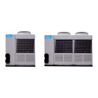
Shows the external view of the 25/35kW chiller module.
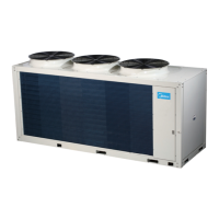
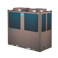
Shows the external view of the 65/80kW chiller module.
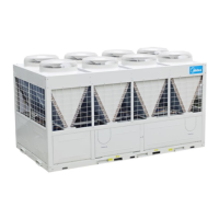
Shows the external view of the 130kW chiller module.
Details the H shape condenser and 360° air suction for enhanced heat exchange efficiency.
Explains the modular system design allowing up to 16 units for flexible capacity and installation.
Describes system behavior during master or slave unit failure for continuous operation.
Explains how slave units alternate duty cycles for balanced lifespan and reliability.
Compares Midea Fast Defrosting with traditional methods, highlighting time savings.
Highlights the use of grooved copper tubes and hydrophilic aluminum foil for improved heat exchange.
Details patented liquid distribution components and 500-step EXV for precise flow control.
Lists various protection mechanisms ensuring safe chiller operation, including pressure, temperature, and flow.
Emphasizes the unit's compact, lightweight design for ease of transport and installation.
Provides detailed technical specifications for SS series models, including capacity, power, compressor, and condenser data.
Provides detailed technical specifications for SP series models, including capacity, power, compressor, and evaporator data.
Shows dimensional drawings and measurements for SS series 25/35kW modules.
Provides dimensional drawings and measurements for SS series 65/80kW modules.
Provides dimensional drawings and measurements for the SS series 130kW module.
Shows dimensional drawings and measurements for SP series 25/35kW modules.
Provides dimensional drawings and measurements for the SP series 65/80kW module.
Illustrates refrigeration system diagrams for SS series 35kW and 65/80kW modules.
Illustrates the refrigeration system diagram for the SS series 130kW module.
Illustrates the refrigeration system diagram for SP series 25/35/65kW modules.
Provides wiring diagrams for SS series models, including MC-SS35/RN1L and MC-SS65/RN1L.
Provides wiring diagrams for SS series models, including MC-SS80/RN1L and MC-SS130/RN1L.
Provides wiring diagrams for SP series models, including MC-SP25-RN1L and MC-SP25M-RN1L.
Provides wiring diagrams for SP series models, including MC-SP35-RN1L and MC-SP35M-RN1L.
Provides the wiring diagram for the SP series model MC-SP65-RN1L.
Illustrates the networking communication schematic for SS series main and auxiliary units.
Illustrates the networking communication schematic for SP series main and auxiliary units.
Details electrical characteristics for SS series models, including power supply and compressor data.
Details electrical characteristics for SP series models, including power supply and compressor data.
Provides cooling capacity tables for SS series (MC-SS35/RN1L, MC-SS65/RN1L) and SP series (MC-SP25-RN1L, MC-SP25M-RN1L).
Provides cooling capacity tables for SP series (MC-SP35-RN1L, MC-SP35M-RN1L, MC-SP65-RN1L).
Provides heating capacity tables for SS series models MC-SS35/RN1L, MC-SS65/RN1L, MC-SS80/RN1L, MC-SS130/RN1L.
Provides heating capacity tables for SP series models MC-SP25-RN1L, MC-SP25M-RN1L, MC-SP35-RN1L, MC-SP35M-RN1L, MC-SP65-RN1L.
Shows exploded view diagrams and component lists for SS series models.
Shows exploded view diagrams and component lists for SP series models.
Lists error and protection codes with descriptions for chiller malfunctions.
Provides common troubles and their possible reasons and solutions.
Offers step-by-step troubleshooting guides for various protection scenarios like high pressure and low pressure.
Details unit installation procedures, including transportation, space, foundation, and damping devices.
Covers pipeline connections, water quality, performance adjustments, flow switches, diagrams, and pump selection.
Lists safety precautions and essential checks before and during wiring installation.
Specifies power supply requirements, including voltage, phase, and fuse ratings for different models.
Outlines rules for wiring connection, emphasizing separation of strong/weak currents and electromagnetic interference.
Provides a step-by-step procedure for performing wiring connections, including grounding and terminal connections.
Details preparatory steps before unit startup, including water system flushing and controller settings.
Describes procedures for conducting a test run, stabilizing temperatures, and final checks.
Highlights key maintenance checks for pressure, equipment protection, and electrical connections.
Explains methods and precautions for removing scale from water-side heat exchangers.
Provides instructions for cleaning, drying, and protecting the unit during winter shutdown.
Guides on replacing parts and procedures for restarting the unit after long-term shutdown.
Details checks for refrigerant levels, leakage detection, and injection procedures.
Outlines the steps for safely disassembling the compressor unit.
Provides information on auxiliary heaters for cold regions and system anti-freezing measures.
Details the PCB layout and components for 35/65/130kW and 80kW modules.
Provides PCB outlook view and component descriptions for 25/35/65kW modules.
Explains the function of each button and provides operating instructions for the wired controller.
Details combinations of keys for setting functions like HYSTERESIS, ADDRESS, and clearing faults.
Describes how to handle unit errors/alarms and the procedure for wired controller installation.
Identifies controller keys and describes their keypad operations and functions.
Guides on setting modes, temperatures, timers, clock, and other parameters via the controller.
Explains how the system handles unit failures and wired controller communication issues.
Introduces the LonWorks gateway, its features, and technical specifications for system integration.
Provides external dimensions and diagrams for different connection methods of the gateway.
Details network variables for setting the main controller and assigned variables for unit modules.
Lists included accessories such as the installation manual and test kit with their usage.
Lists optional accessories like wired controllers and gateways with their specifications.
Provides characteristic data sheets for pipe, ambient, inlet, and outlet water temperature sensors.
Details the temperature-resistance characteristic sheet for the digital compressor discharge temperature sensor.