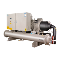
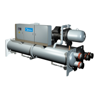
Flooded type water cooled screw chiller (PCB Control) MCAC-CTSM-2012-11
79
V. Control
1. Description of Energy Adjustment
Energy adjustment may be controlled by either entering water temperature or leaving water
temperature in case of operation of single-module unit, and it can only be controlled by entering
water temperature in case of multi-module interconnection.
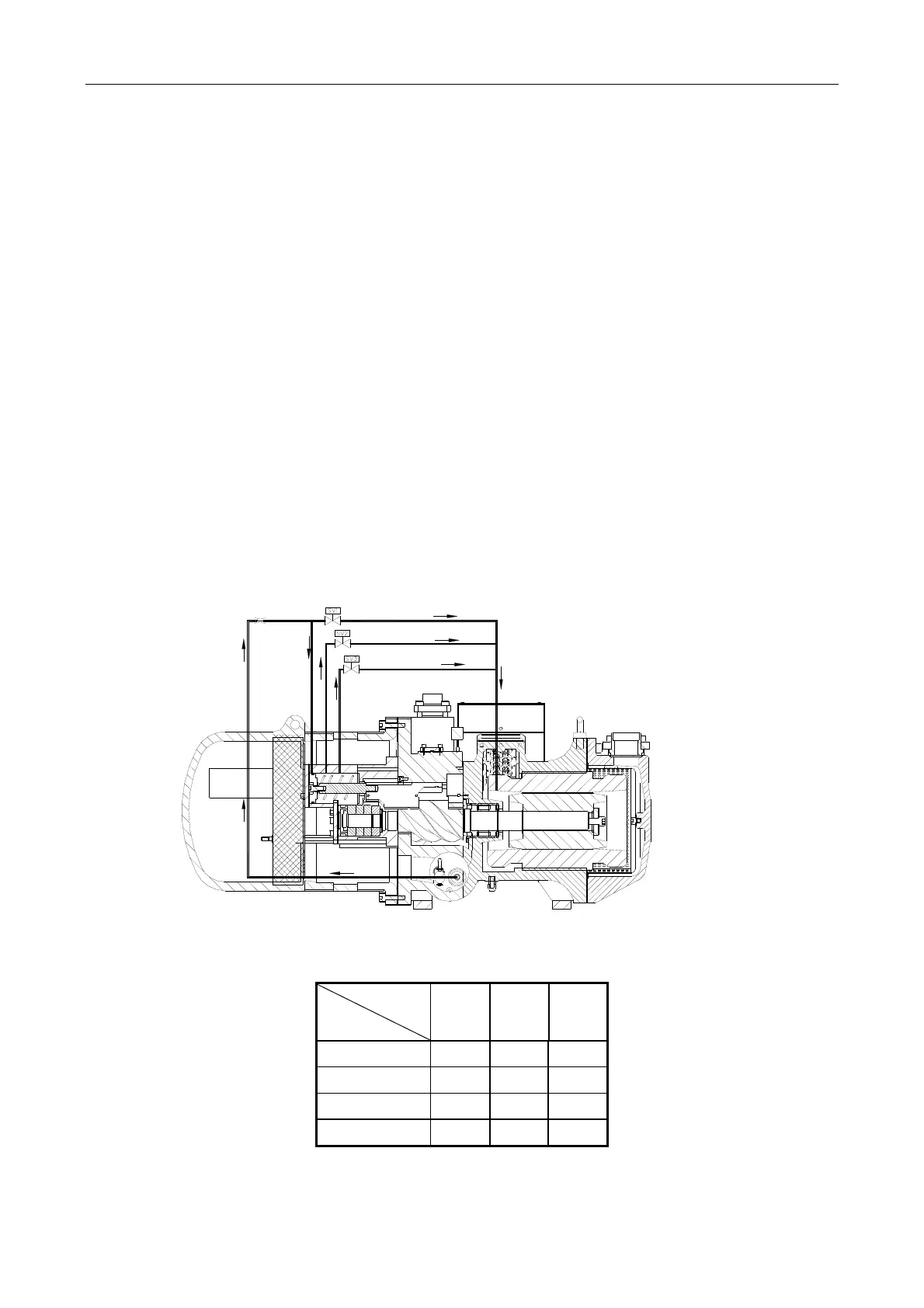
Compressor Capacity Adjustment
The capacity output of the unit is determined by the valid length of slide valve which is controlled by
3 solenoid valves. The control system cycles compressors, loaders, and minimum load control
valves to maintain the user configured leaving (or entering) chilled water temperature set point.
Temperature sensors transfer temperature signals to PCB which will calculate the optimum time to
add or subtract capacity stages. Special algorithm programmed in PCB will try to maintain the
Control Point at the desired set point.
4-stage control (50%~100%)
The 4-step capacity control system is made of one slider, three NC solenoid valves and one piston
with adjustable range of 25%, 50%, 75% and 100%. The principle of capacity control is by moving
the slider to allow partial refrigerant to bypass back to the intake and regulate the refrigerant flow.
Solenoid valve activating table of four-stage capacity control
SV
Status
SV1
(NC)
SV2
(NC)
SV3
(NC)
100% OFF OFF OFF
75% OFF OFF ON
50% OFF ON OFF
25%(startup) ON OFF OFF
ON: energize, OFF: de-energize
Startup: 25% loading