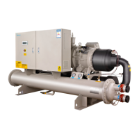
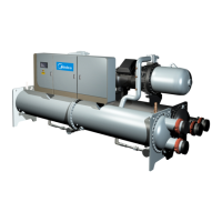
Flooded type water cooled screw chiller (PCB Control) MCAC-CTSM-2012-11
83
outlet of both the Condenser and Evaporator and the length A of water flow switch should be 5 times
the length of the pipe diameter. Adjust the target of water flow switch according to the water pipe
specification (Refer to the manufacturing manual). Water flow switch is connected to the terminals in
control cabinet; refer to the electrical wiring diagram for details.
When power is supplied to the device, PCB control begins to detect water flow after water pumps
running for 3 minutes. If water flow switch keeps open for 5s, the chiller will stop. It needs manually
reset. Perform the steps below to solve the problem.
1. Check to confirm that all strainers are clean, valves are open and pumps are running. For the case
of VFD controlled pumps, ensure that the minimum frequency set point has not been changed.
2. Measure the pressure drop across the heat exchangers (Read the difference of pressure gauges
installed on the inlet and outlet) and using Appendix water pressure drop curves, calculate the flow
and compare this to the system requirements.
3. If the measured flow rate through the heat exchanger agrees with the system requirements.
Possible reason of the malfunction may be wrong installation direction of the switch, inadequate
depth of the target, broken switch or wiring looseness, etc. New switch must be replaced if problem is
switch itself.
5. Demand Limit
Auto unload control function
For step control unit: When compressor continuously operates at chilled water temperature > 12°C more
than 30 mins, unload to 50%; regain 100% load after 10 mins later.
For stepless control unit: When compressor continuously operates at chilled water temperature > 12°C
more than 30 mins, unload to 50%; regain 100% load after 10 mins later.
Operation current limit control
During unit running, it will unload immediately when the current reach 95% of set point and will not
execute capacity increase action. Stop unloading until compressor unloads to 50%. After unloading
operation for 10mins and the current value <=70% of set point and the unit meets loading condition, the
unit will reload step by step.
6. EXV operation& wiring
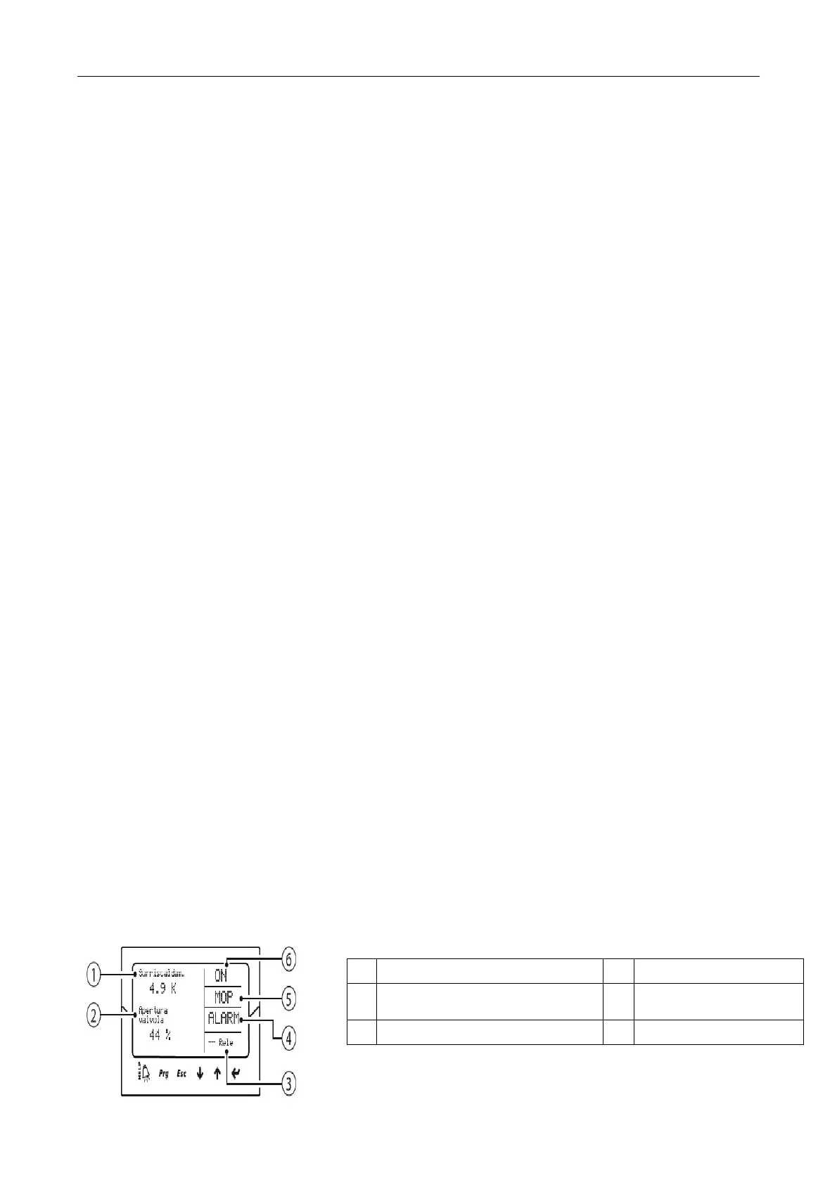
User interface consists of five components of the LED display operating status, the table below:
Display and keypad
Graphical display with two kinds of system variables, the drive control of the state, protection
function is activated, and the alarm and relay output status
1 Display first kinds of variables 4 Alarm
2
Display second kinds of
variables
5 Start of the protection
3 Relay output status 6 Control state