Flooded type water cooled screw chiller (PCB Control) MCAC-CTSM-2012-11
84
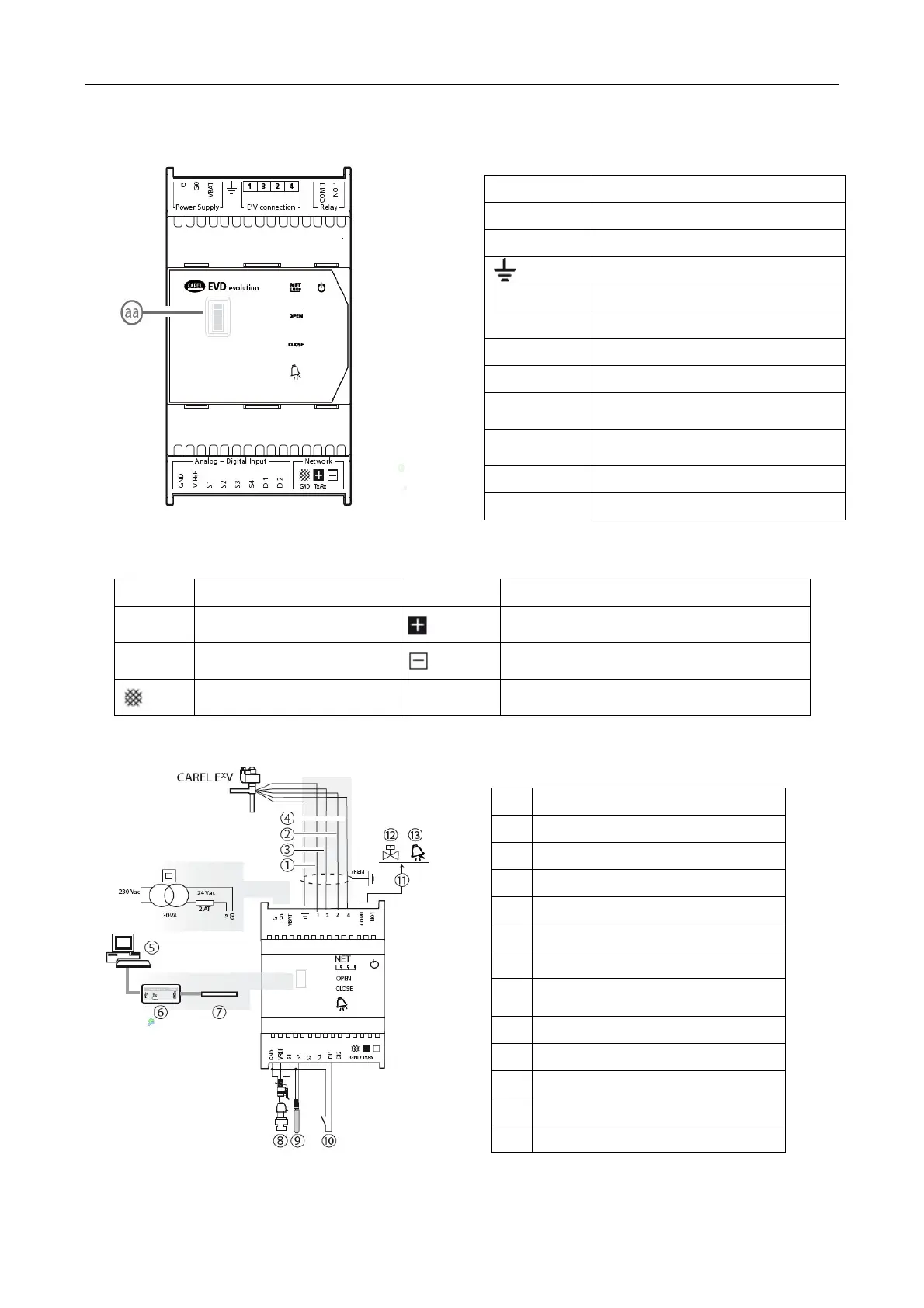
General wiring diagram
Terminal
E
xplanation
G\G0 Power supply
VABT Emergency Power Supply
Functional ground
1,2,3,4 Stepper motor power supply
COM1,NO1 Alarm Relay
GND Signal Ground
VREF Sensor power supply
S1
Sensor 1 (pressure) or an external
signal 4 to 20mA
S2
Sensor 2 (temperature) or 0 to
10V external signal
S3 Sensor 3 (pressure)
S4 Sensor 4 (temperature)
Terminal
E
xplanation
Terminal
E
xplanation
DI1 Digital input 1
Connection tLAN, pLAN, RS485, Modbus
® terminal
DI2 Digital input 2
Connection pLAN, RS485, Modbus ®
terminal
Connection tLAN, pLAN,
RS485, Modbus ® terminal
aa
Service port, after removal of the cover
need to be connected LED
1 Green
2 yellow
3 Brown
4 white
5 sets of personal computers
6 USB / tLAN converter
7 Adapter
8
ratio of pressure sensor -
evaporation pressure
9 NTC suction temperature
10 start-controlled digital input 1
11 free contacts (up to 230Vac)
12 solenoid valve
13 warning signs