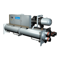
Flooded type water cooled screw chiller (PCB Control) MCAC-CTSM-2012-11
67
e) The evaporator refrigerant level slightly laps last tubes row by checking the sight glass installed on
each evaporator for a visual inspection.
f) The condenser refrigerant level to be included between the condensing and the sub-cooling sections
by checking the sight glass installed on each condenser for a visual inspection.
5. Verify the sight glass on the liquid piping to be fully charged. If one of the above parameters exceeds
the limits, unit may require an additional refrigerant charge.
Note: Refrigerant removing and drain operation must be performed by qualified personnel using correct
material. Inappropriate maintenance could lead to refrigerant or pressure loss. Do not discharge the
refrigerant or the lubricant oil into the environment. Always use a proper recovery system.
Refer to Physical Data tables supplied in the IOM manual book). Immediately ahead of orifice baffle (see
Fig.) is a factory-installed liquid line service angle valve. Each angle valve has a1 5/8-in. threaded
connection for charging liquid refrigerant. Connect the refrigerant drum to the gauge port on the liquid
line shutoff valve and purge the charging line between the refrigerant cylinder and the valve. Then open
the valve to the mid-position.
Turn on both the cooling tower water pump and chilled water pump and allow water to circulate through
the condenser and the chiller.
IMPORTANT: When adding refrigerant to the unit, circulate water through evaporator continuously to
prevent freezing and possible damage to the evaporator. Do not overcharge, and never charge liquid
into the low-pressure side of system.
If the system is under a vacuum, stand the refrigerant drum with the connection up, and open the drum
and break the vacuum with refrigerant gas to a saturated pressure above freezing.
With a system gas pressure higher than the equivalent of a freezing temperature, invert the charging
cylinder and elevate the drum above the condenser. With the drum in this position, valves open, water
pumps operating, liquid refrigerant will flow into the condenser. Approximately 75% of the total
requirement estimated for the unit can be charged in this manner.
After 75% of the required charge has entered the condenser, reconnect the refrigerant drum and
charging line to the service valve on the bottom of the evaporator. Again purge the connecting line, stand
the drum with the connection up, and place the service valve in the open position.
Before replacing electronic expansion valve of the system, pressure sensor sampling stop valve, low
pressure pipeline, etc. force the refrigerant in the liquid part of the system.
The particular steps are: (take careful consideration before continuing with the following steps)`
a Close the dry filter angle valve of the system.
b Start up the unit, and emergently stop the unit when the gas in the system is below 0.5bar.
c Close the liquid/air valve of the compressor.

 Loading...


