EasyManuals Logo

Midea MC-SU60-RN1L Service Manual

Midea MC-SU60-RN1L
101 pages
To Next Page IconTo Next Page
To Previous Page IconTo Previous Page
Page #44 background imageLoading...
Page #44 background image
Aqua Tempo Super II
201709 43
Part
4 - Diagnosis and Troubleshooting
Table 4-2.6: Compressor inverter module PCB
Label in
Figure
4-2.2
Code
Content
Voltage
1
SW1
Inverter module address switch
-
2
IC14
EEPROM
-
3
CN9
CN10
Inverter module communication port
2.5-2.7V DC
4
W
Compressor connections
V
UV
= V
Uw
= V
VW
0-380V AC
5
V
6
U
7
N
IPM module input port N
V
PN
= 540V DC
8
P
IPM module input port P
9
N2
IPM module protection port N2
V
P2N2
= 540V DC
10
P2
IPM module protection port P2
11
CN15
Power supply inverter module board
310V DC
12
N1
IPM module power supply port N1
V
P1N1
=540V DC
13
P1
IPM module power supply port P1
14
CN3
Three-phase bridge rectifier positive port
540V DC relative
to N
15
CN11
Three-phase bridge rectifier control port
15V DC
16
CN1
Reactor port
540V DC relative
to N
17
CN4
Capacity positive port
540V DC relative
to N
Compressor Inverter Module PCB field setting 2.3.1
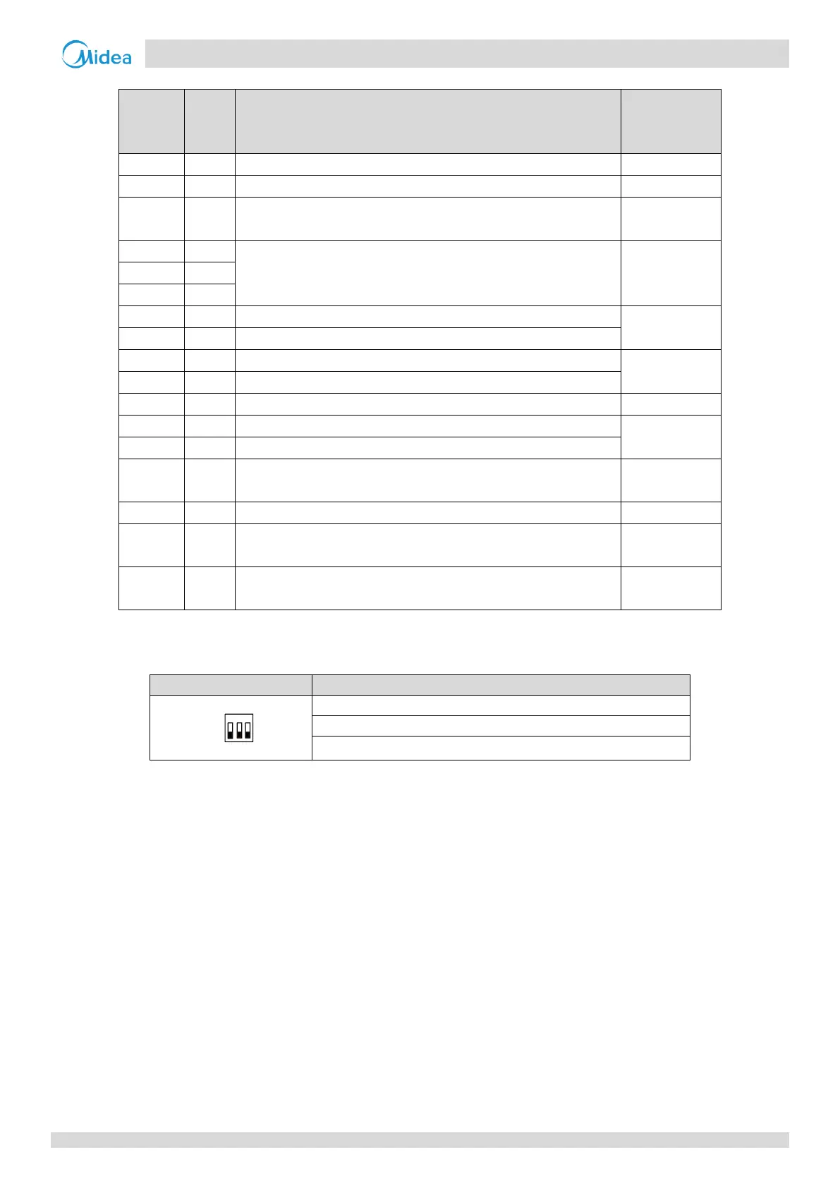
Table 4-2.7: Compressor inverter module PCB switch settings
Switch
Description
SW1
000: MC-SU30-RN1L compressor inverter module address setting
000: MC-SU60-RN1L compressor A inverter module address setting
001: MC-SU60-RN1L compressor B inverter module address setting
OFF
ON
1 2 3

Table of Contents

Other manuals for Midea MC-SU60-RN1L

Questions and Answers:

Question and Answer IconNeed help?

Do you have a question about the Midea MC-SU60-RN1L and is the answer not in the manual?

Midea MC-SU60-RN1L Specifications

General IconGeneral
BrandMidea
ModelMC-SU60-RN1L
CategoryChiller
LanguageEnglish

Related product manuals