EasyManuals Logo

Midea MC-SU60-RN1L Service Manual

Midea MC-SU60-RN1L
101 pages
To Next Page IconTo Next Page
To Previous Page IconTo Previous Page
Page #45 background imageLoading...
Page #45 background image
Aqua Tempo Super II
44 201709
Midea Aqua Tempo Super II
Service Manual
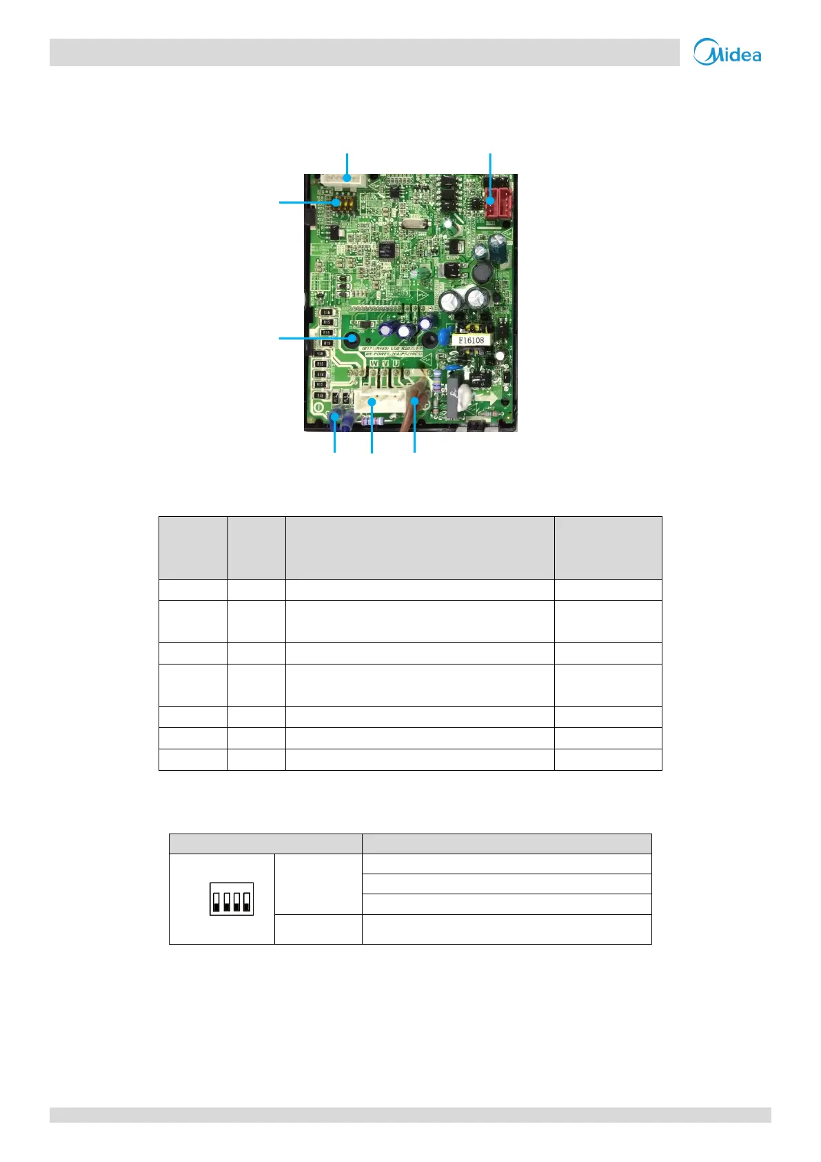
2.4 Fan Module Board
Figure 4-2.3: Fan module PCB
1 2
7
6
5 4 3
Table 4-2.8: Fan module PCB
Label in
Figure
4-2.3
Code
Content
Voltage
1
CN2
EEPROGRAM
-
2
CN1
CN4
Communication port for inverter module
2.5-2.7 DC
3
P
Power supply for inverter module
V
PN
= 310V DC
4
CN3
Power supply for the fan motor
V
UV
= V
Uw
= V
VW
0-310V AC
5
N
Power supply for inverter module
V
PN
= 310V DC
6
U3
IPM
-
7
SW1
Address for the inverter module
-
Fan Module PCB field setting 2.4.1
Table 4-2.9: Fan module PCB switch settings
Switch
Description
SW1
SW1-1
SW1-2
00: MC-SU30-RN1L fan module address setting
00: MC-SU60-RN1L fan module A address setting
01: MC-SU60-RN1L fan module B address setting
SW1-3
SW1-4
Reserved
OFF
ON
1 2 3 4

Table of Contents

Other manuals for Midea MC-SU60-RN1L

Questions and Answers:

Question and Answer IconNeed help?

Do you have a question about the Midea MC-SU60-RN1L and is the answer not in the manual?

Midea MC-SU60-RN1L Specifications

General IconGeneral
BrandMidea
ModelMC-SU60-RN1L
CategoryChiller
LanguageEnglish

Related product manuals