Aqua Tempo Super II
201709 19
4.3 Startup Control for Heating Operation
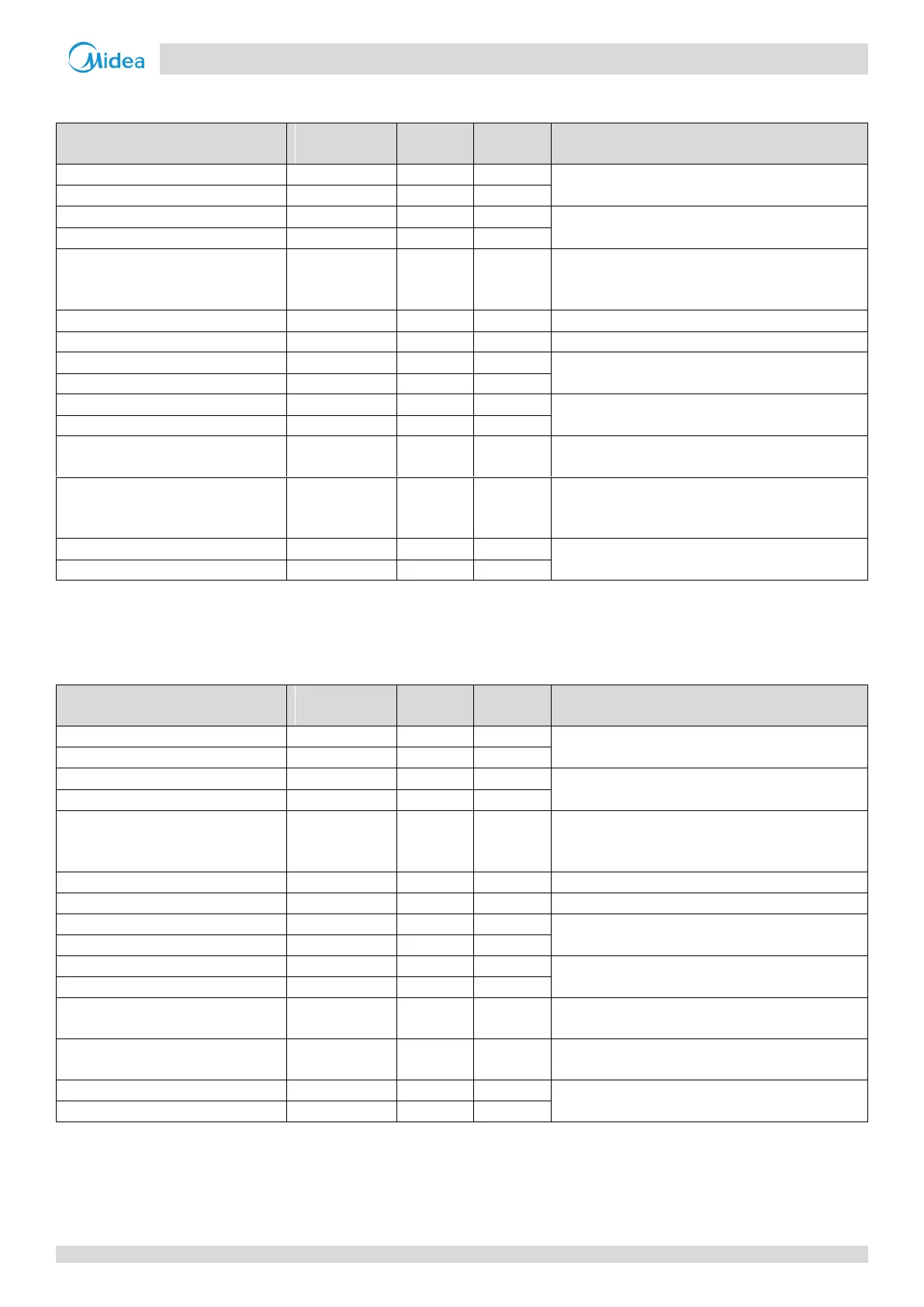
Table 3-4.1: Component control during startup in heating mode
Control functions and states
Compressor startup program selected according to
ambient temperature
and discharge temperature
1
Controlled according to ambient temperature
Electronic expansion valve
Position (steps) from 0 (fully closed) to 480 (fully
open), controlled according to outdoor ambient
temperature, unit capacity.
On after the compressor startup for 10s
Solenoid valve (oil balance)
Closed for 200s, open for 600s, then closed
Water side heat exchanger heater 1
According to water side heat exchanger
anti-freezing temperature (Taf)
Water side heat exchanger heater 2
Controlled according to ambient temperature, water
inlet temperature and water outlet temperature
Electric auxiliary heater
Controlled according to ambient temperature and
total water outlet temperature after the compressor
is on
Controlled according to ambient temperature and
discharge temperature
Notes:
1. Refer to Figure 3-4.1, Figure 3-4.2 and in Part 3, 4.2 “Compressor Startup Program”.
4.4 Startup Control for Cooling Operation
Table 3-4.2: Component control during startup in cooling mode
Control functions and states
Compressor startup program selected according to
ambient temperature and discharge temperature
1
Controlled according to air side heat exchanger
refrigerant total outlet temperature (Tz/7)
Electronic expansion valve
Position (steps) from 0 (fully closed) to 480 (fully
open), controlled according to outdoor ambient
temperature, outdoor unit initial frequency
Solenoid valve (oil balance)
Closed for 200s, open for 600s, then closed
Water side heat exchanger heater 1
According to water side heat exchanger
anti-freezing temperature (Taf)
Water side heat exchanger heater 2
Controlled according to ambient temperature, water
inlet temperature and water outlet temperature
Controlled according to ambient temperature and
discharge temperature
Notes:
1. Refer to Figure 3-4.1, Figure 3-4.2 and in Part 3, 4.2 “Compressor Startup Program”.
 Loading...