Aqua Tempo Super II
201709 73
Part
4 - Diagnosis and Troubleshooting
xL2 troubleshooting 4.12.8
Step 1: Check inverter module
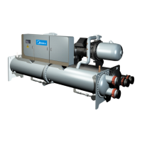
Check the DC voltage between terminals P and N. The normal value is 510-580V, if the voltage is higher than 580V, go
to Step 2.
Figure 4-4.9: Inverter module terminals
Step 2: Check inverter module
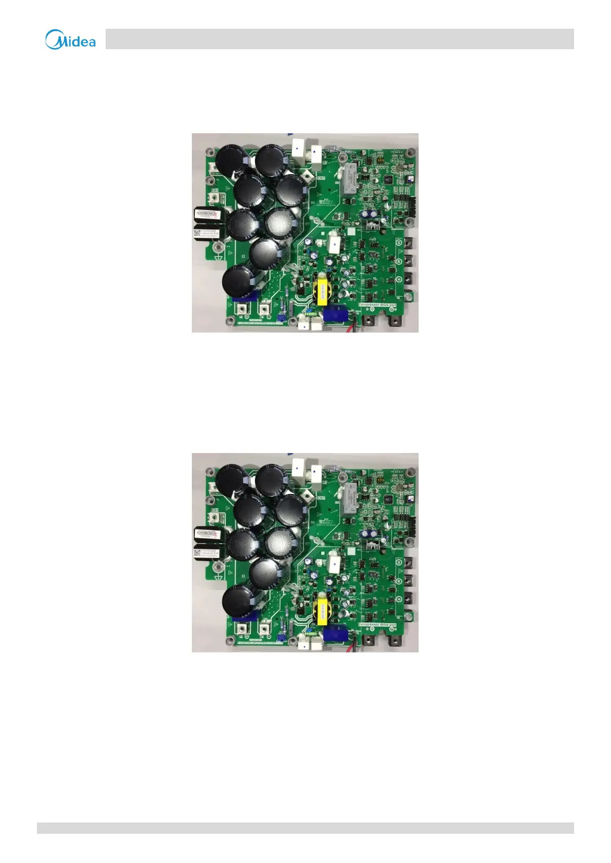
Check the voltage between terminals P and N on the capacitor board. The normal value is 510-580V. If the voltage is
not in the normal range, there is a problem with the electrolytic capacitor power supply. Check the power supply for
high or unstable voltage. If the power supply voltage value is normal, then the main PCB has malfunctioned and
needs to be replaced.
Figure 4-4.10: Inverter module terminals
xL8/xL9 troubleshooting 4.12.9
Step 1: Check compressor
The normal resistances of the inverter compressor are 0.7-1.5Ω among U V W and infinite between each of U V W
and ground. If any of the resistances differ from these specifications, the compressor has malfunctioned.
Refer to Figures 4-4.4 and 4-4.5 in Part 4, 4.12.6 “xL0 troubleshooting”. If the resistance values are normal, go to Step
2.
Step 2: Check compressor and main PCB
If there is another unit nearby (either in the same system or another system) that is operating normally, its electric
 Loading...