Application c
13
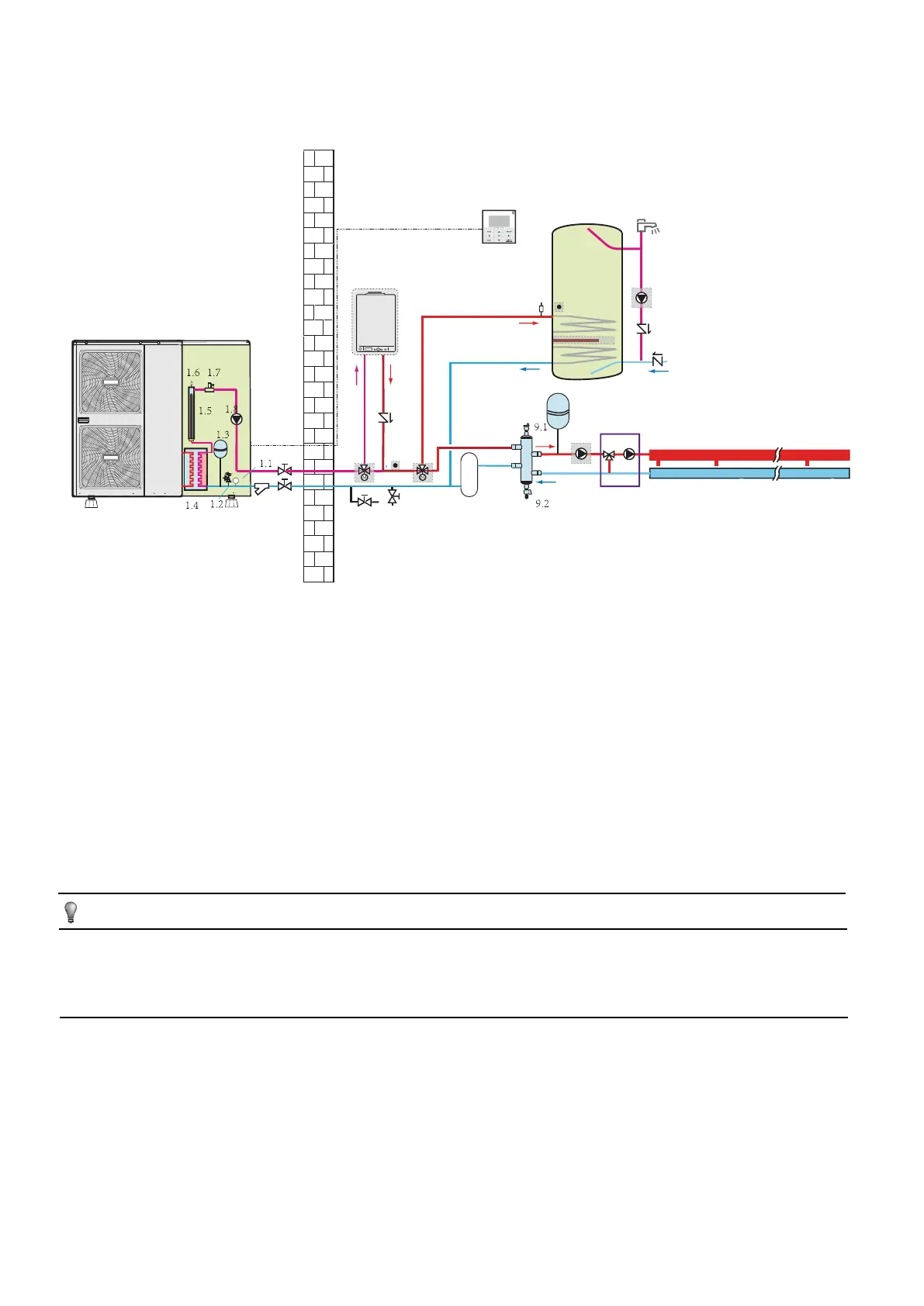
Boiler provide heat for space heating and domestic water heating, but the boiler and outdoor unit are connect in series.
If application c is selected, the control cable connect to the boiler should also connect to the 3-way valve (25), that is to say the 3-way valve(25)
and boiler should work simultaneously.
FHL1 FHL2 FHLn
AHS
.......
11
10
12
1
32
6 7
8
9
16
14
13.1
13
17
17
15
13.2
25
17
23
19
4
24.1
24
13.3
1 outdoor unit
1.1 manometer
1.2 pressure relief valve
1.3 expansion vessel
1.4 plate heat exchanger
1.5 backup heater
1.6 air purge valve
1.7 flow switch
1.8 P_i: circulation pump inside
the unit
2 y-shape filter
3 stop valve (field supply)
4 user interface
6 drain valve(field supply)
7 fill valve(field supply)
8 buffer tank(field supply)
9 balance tank(field supply)
9.1 air purge valve
9.2 drain valve
10 expansion vessel(field supply)
11 P_o: outside circulation pump
(field supply)
12 collector(field supply)
13 domestic hot water tank(field
supply)
13.1 booster heater
13.2 heat exchanger coil
13.3 air purge valve
14 T5:temperature sensor
15 hot water tap(field supply)
16 P_d: DHW pump(field supply)
17 non-return valve(field supply)
19 SV1: 3-way valve(field supply)
23 T1B: temperature sensor(field
supply)
24 mixing station(field supply)
24.1 P_c: mixing pump
25 3-way valve(field supply)
FHL 1...n floor heating loop
AHS additional heating
source(boiler)
NOTE
If the volume of balance tank(9) is larger than 30L, the buffer tank(8) is unnecessary, otherwise the buffer tank(8) should be installed and the
total volume of balance tank and buffer tank should larger than 30L.. The drain valve (6) should be installed at the lowest positon of the system.
For the 5/7/9kW unit, the backup heater (1.5) is not integrated in the outdoor unit. An independent backup heater can be selected and installed
in the door.Temperature sensor T1B must be installed at the outlet of AHS, and connect to the corresponding port in the main control board of
hydraulic module(refer to 9.2.3 Main control board of hydraulic module).
Operation
When heating is required, either the unit or the boiler starts operating, depending on the outdoor temperature (refer to 10.7 field setting/OTHER
HEATING SOURCE).
■ As the outdoor temperature is measured via the outdoor unit air thermistor, make sure to install the outdoor unit in the shade, so that it is not i
influenced by the sun’s heat.
■ Frequent switching can cause corrosion of the boiler at an early stage. Contact the boiler manufacturer.
■ During heating operation of the unit, the unit will operate to achieve the target water flow temperature set on the user interface. When weather
dependent operation is active, the water temperature is determined automatically depending on the outdoor temperature.

 Loading...
