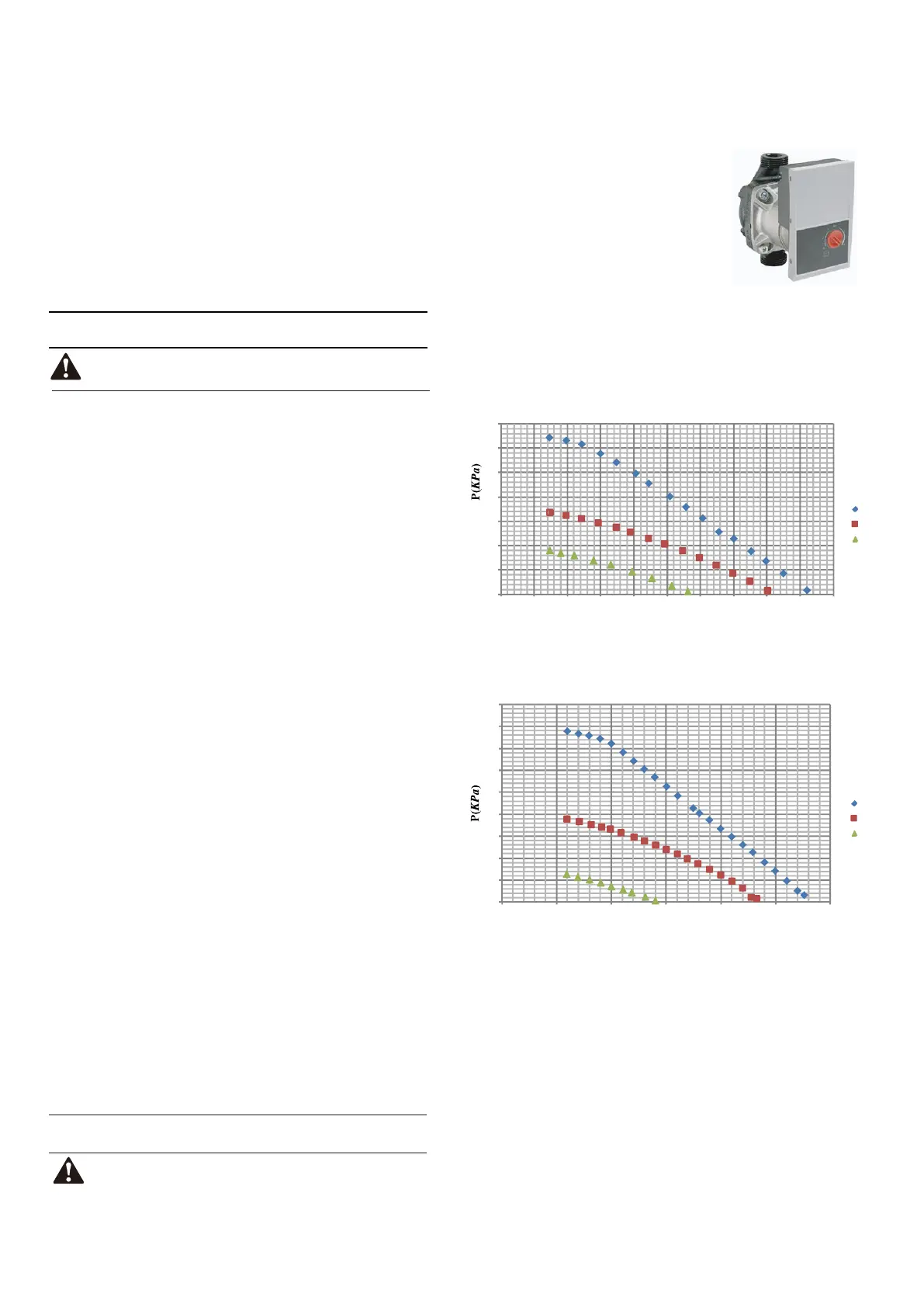
The available external static pressure function for water flow is
shown in the graph below.
10.6 Setting the pump speed
The default setting is the highest speed (III).
If the water flow in the system is too high
the speed can be
set to low (I).
The pump speed can be selected by
adjusting the red knob on the pump. The
notch point indicates pump speed.
5. Ground wiring
Make sure that the ground wires have been connected properly
and that the ground terminals are tightened.
6. Internal wiring
Visually check the switch box for loose connections or damaged
electrical components.
7. Mounting
Check that the unit is properly mounted, to avoid abnormal noises
and vibrations when starting up the unit.
8. Damaged equipment
Check the inside of the unit for damaged components or
squeezed pipes.
9. Refrigerant leak
Check the inside of the unit for refrigerant leakage. If there is a
refrigerant leak, call your local dealer.
10.Power supply voltage
Check the power supply voltage on the local supply panel. The
voltage must correspond to the voltage on the identification label
of the unit.
11.Air purge valve
Make sure the air purge valve is open (at least 2 turns).
2. Fuses, circuit breakers, or protection devices
Check that the fuses or the locally installed protection devices are
of the size and type specified in the chapter 14 Technical
specifications. Make sure that no fuses or protection devices
have been bypassed.
3. Backup heater circuit breaker
Do not forget to turn on the backup heater circuit breaker in the
switchbox (it depends on the backup heater type). Refer to the
wiring diagram.
4. Booster heater circuit breaker
Do not forget to turn on the booster heater circuit breaker (applies
only to units with optional domestic hot water tank installed).
10.5 Powering up the unit
Operating the system with closed valves will damage the
circulation pump!
12.Shut-off valves
Make sure that the shut-off valves are fully open
When power to the unit is turned on, "1%~99%" is displayed on the
user interface during initialization. During this process the user
interface cannot be operated.
0
10
20
30
40
50
60
70
80
90
0.3 0.8 1.3 1.8 2.3 2.8 3.3
Flowrate(m³/h)
available external stac pressure VS flowrate
(1-phase 10-16kW + 3-phase 12~16kW)
Ⅲ
Ⅱ
Ⅰ
0
10
20
30
40
50
60
70
0.3 0.5 0.7 0.9 1.1 1.3 1.5 1.7 1.9 2.1 2.3
Flowrate(m³/h)
available external stac pressure VS flowrate
(5/7/9kW)
Ⅲ
Ⅱ
Ⅰ
Checks before initial start-up
10.4 Pre-operation checks
10.3 Initial start-up at low outdoor ambient temperatures
During initial start-up and when water temperature is low, it is
important that the water is heated gradually. Failure to do so may
result in concrete floors cracking due to rapid temperature change.
Please contact the responsible cast concrete building contractor for
further details.
To do so, the lowest water flow set temperature can be decreased to
a value between 25°C and 35°C by adjusting the FOR SERVICEMAN.
Refer to "FOR SERVICEMAN/special function/preheating for floor" .
Switch off the power supply before making any connections.
DANGER
After the installation of the unit, check the following before switching
on the circuit breaker:
1. Field wiring
Make sure that the field wiring between the local supply panel and
unit and valves (when applicable), unit and room thermostat (when
applicable), unit and domestic hot water tank, and unit and backup
heater box have been connected according to the instructions
described in the chapter 9.6 Field wiring, according to the wiring
diagrams and to local laws and regulations.
38
38

 Loading...
