During filling, it might not be possible to remove all air in the
system. Remaining air will be removed through the automatic
air purge valves during the first operating hours of the system.
Topping up the water afterwards might be required.
■ The water pressure indicated on the manometer will vary
depending on the water temperature (higher pressure at
higher water temperature).
However, at all times water pressure should remain
above 0.3 bar to avoid air entering the circuit.
■ The unit might drain-off too much water through the
pressure relief valve.
■ Water quality must be according to "Safe Drinking water
Act "
The ground fault circuit interrupter must be a high- speed
type breaker of 30 mA (<0.1 s).
The complete water circuit including all piping, must be insulated to
prevent condensation during cooling operation and reduction of the
heating and cooling capacity as well as prevention of freezing of the
outside water piping during winter. The thickness of the sealing
materials must be at least 13 mm with λ= 0.039 W/mK in order to
prevent freezing on the outside water piping.
If the temperature is higher than 30°C and the humidity is higher than
RH 80%, then the thickness of the sealing materials should be at
least 20 mm in order to avoid condensation on the surface of the seal.
■ This unit is equipped with an inverter. Installing a phase advancing
capacitor not only will reduce the power factor improvement effect,
but also may cause abnormal heating of the capacitor due to high-
frequency waves. Never install a phase advancing capacitor as it
could lead to an accident.
9.6.1 Precautions on electrical wiring work
■ Fix cables so that cables do not make contact with the pipes
(especially on the high pressure side).
■ Secure the electrical wiring with cable ties as shown in figure
so that it does not come in contact with the piping, particularly on
the high-pressure side.
■ Make sure no external pressure is applied to the terminal
connectors.
■ When installing the ground fault circuit interrupter make sure
that it is compatible with the inverter (resistant to high frequency
electrical noise) to avoid unnecessary opening of the ground fault
circuit interrupter.
9.6.2 Overview
The illustration below gives an overview of the required field wiring
between several parts of the installation. Refer also to "8 Typical
application examples".
Be aware of the hygroscopic property of glycol. It absorbs
moisture from the environment.
Leaving the cap off the glycol container causes the
concentration of water to increase. The glycol concentration
is then lower and the water could freeze.
Preventive actions must be taken to ensure minimal
exposure of the glycol to air.
Also refer to "10.3 Pre-operation checks/Checks before initial
start-up"
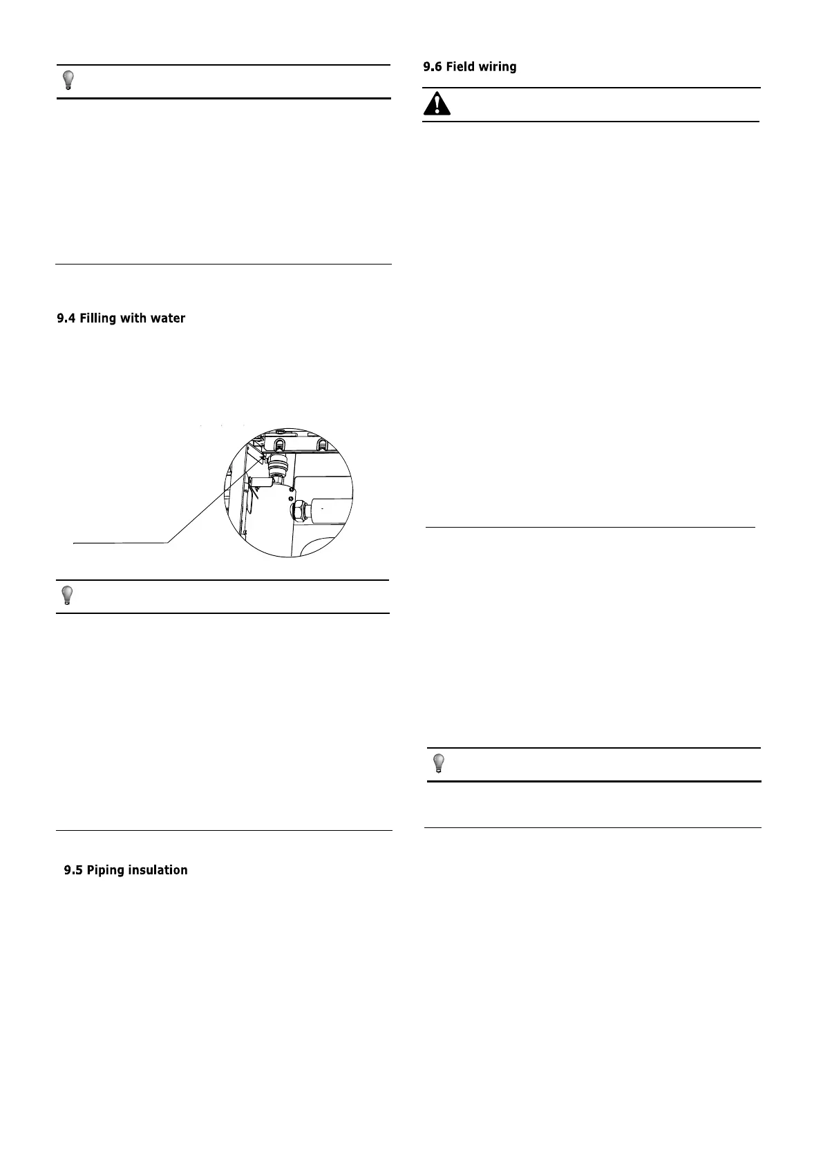
1. Connect the water supply to the fill valve and open the valve.
2. Make sure the automatic air purge valve is open (at least 2 turns).
3. Fill with water until the manometer indicates a pressure of
approximately 2.0 bar. Remove air in the circuit as much as
possible using the air purge valves. Air present in the water circuit
might cause malfunctioning of the backup heater.
■ Be sure to use a dedicated power supply. Never use a
power supply shared by another appliance.
■ Be sure to establish a ground. Do not ground the unit to
a utility pipe, surge protector, or telephone ground.
Incomplete grounding may cause electrical shock.
■ Be sure to install a ground fault circuit interrupter (30 mA).
Failure to do so may cause electrical shock.
■ Be sure to install the required fuses or circuit breakers.
NOTE
NOTE
■
■
■
■ A main switch or other means of disconnection, having a c
ontact separation in all poles, must be incorporated in the fixed
wiring in accordance with relevant local laws and regulations.
■ Switch off the power supply before making any
connections.
■ Use only copper wires.
■ Never squeeze bundled cables and make sure they do not
come in contact with the piping and sharp edges. Make sure no
external pressure is applied to the terminal connections.
■ All field wiring and components must be installed by a
licensed electrician and must comply with relevant local
laws and regulations.
■ The field wiring must be carried out in accordance with the
wiring diagram supplied with the unit and the instructions
given below.
NOTE
WARNING
Do not fasten the black
plastic cover on the vent
valve at the topside of the
unit when the system is
running. Open air purge
valve, turn anticlockWise at
least 2 full turns to release
air from the system.
29

 Loading...
