32
9.6.3 Precautions on wiring of power supply
■ UUse a round crimp-style terminal for connection to the power
supply terminal board. In case it cannot be used due to unavoidable
reasons, be sure to observe the following instructions.
Field wiring guidelines
■ Most field wiring on the unit is to be made on the terminal block
inside the switch box. To gain access to the terminal block,
remove the switch box service panel (door 2).
■ Fix all cables using cable ties.
■ A dedicated power circuit is required for the backup heater.
■ Installations equipped with a domestic hot water tank (optional)
require a dedicated power circuit for the booster heater.
Please refer to the domestic hot water tank Installation &
Owner's Manual.
Secure the wiring in the order shown below.
■ Lay out the electrical wiring so that the front cover does not rise up
when doing wiring work and attach the front cover securely (see figure).
■ Follow the electric wiring diagram for electrical wiring works (the
electric wiring diagrams are located on the rear side of door 2.
■ Install the wires and fix the cover firmly so that the cover may
be fit in properly.
The ground fault circuit interrupter must be a high-speed
type breaker of 30 mA (<0.1 s).
Switch off all power including the unit power supply and
backup heater and domestic hot water tank power supply
(if applicable) before removing the switch box service panel.
- Do not connect different gauge wires to the same power supply
terminal. (Loose connections may cause overheating.)
- When connecting wires of the same gauge, connect them
according to the figure below.
■ Use the correct screwdriver to tighten the terminal screws.
Small screwdrivers can damage the screw head and prevent
appropriate tightening.
■ Over-tightening the terminal screws can damage the screws.
■ Attach a ground fault circuit interrupter and fuse to the power
supply line.
■ In wiring, make certain that prescribed wires are used, carry out
complete connections, and fix the wires so that outside force cannot
affect the terminals.
Door 1: compressor compartment and electrical parts: XT1
Power circuit and cable requirements
(a) Stated values are maximum values (see electrical data for exact
values).
NOTE
■ Be sure to use a dedicated power circuit for the backup
heater. Never use a power circuit shared by another
appliance.
■ Use the same dedicated power supply for the unit,
backup heater and booster heater (domestic hot water
tank).
WARNING
This power circuit must be protected with the required safety devices
according to local laws and regulations.
Select the power cable in accordance with relevant local laws and
regulations. For the maximum running current of the backup heater,
refer to the table below.
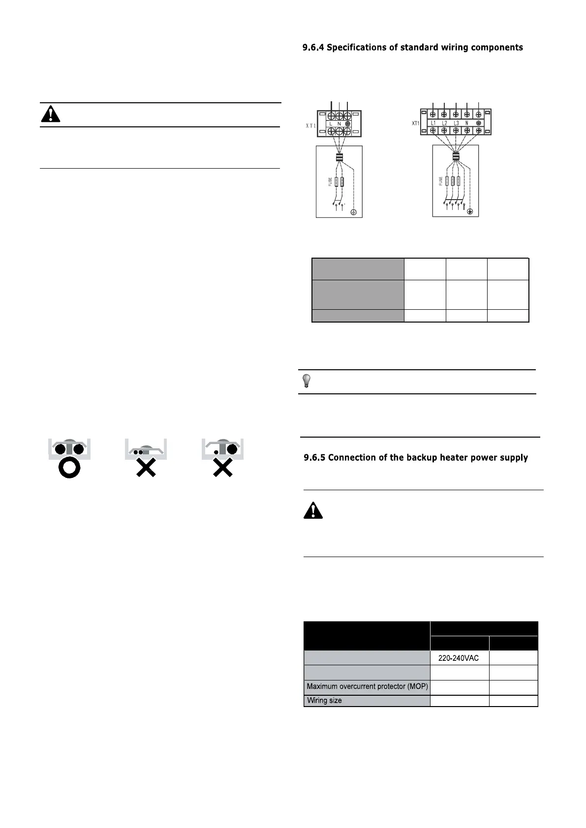
3-phase1-phase
YLPPUSREWOPTINUROODTUO
SPL
A B C N
1-phase
5/7/9 kW
1-phase
10~16kW
3-phase
12~16kW
Maximum overcurrent
protector(MOP)
25 40 20
Wiring size
4 mm
2
6 mm
2
4 mm
2
Minimum circuit amps (MCA)
Backup heater nominal voltage
20
14.3
10
6
380-415VAC
3kW 4.5kW
Backup heater capacity
1-phase 3-phase
YLPPUSREWOPTINUROODTUO
SPL
L N
3.3mm
2.1mm
2
2

 Loading...
