13.3 PARAMETERS CHECK IN THE UNIT
To check the parameters of hydraulic box, open door 2 and you’ll
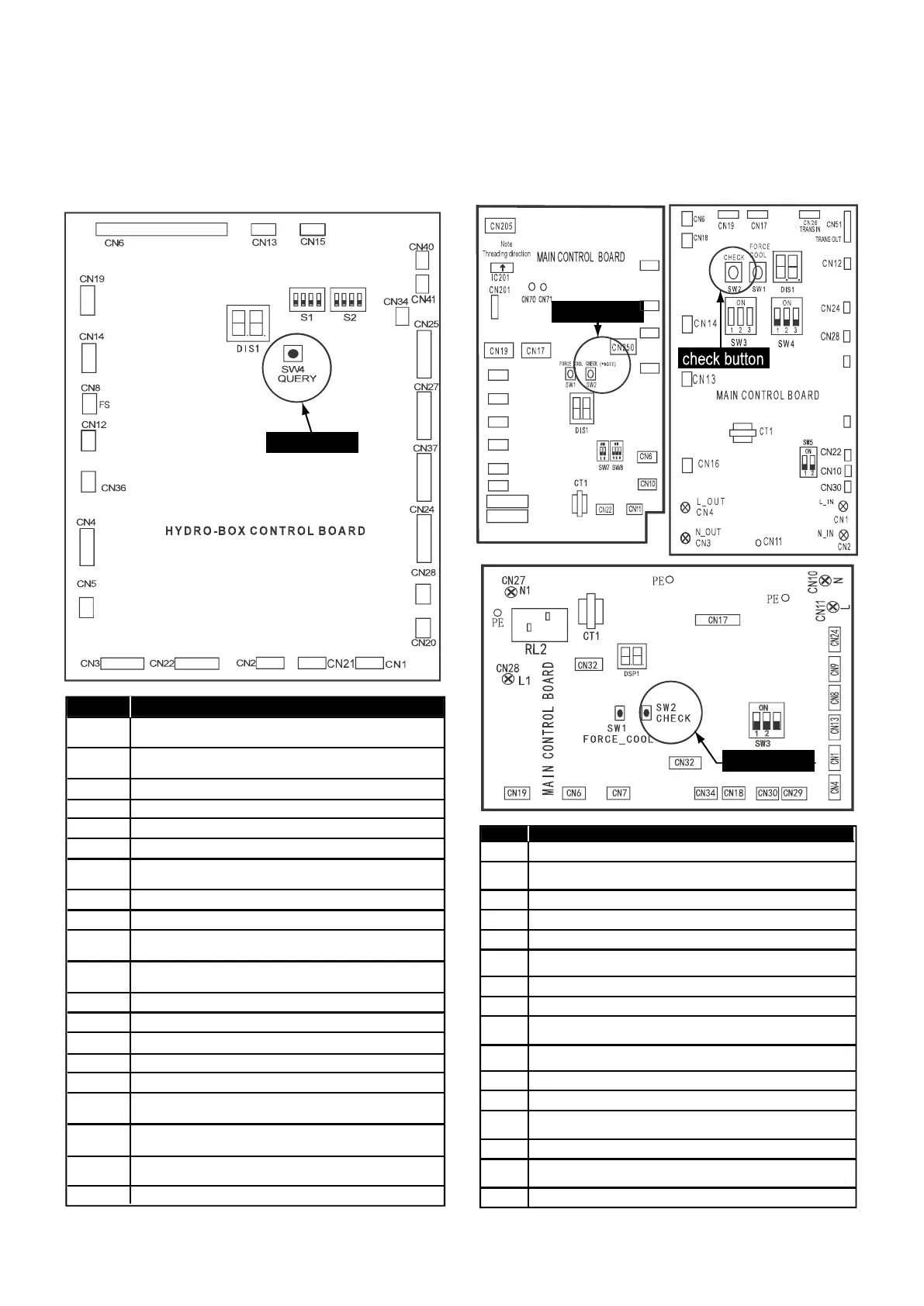
see the PCB like following, the digital display will show the
temperature of outlet water in normal condition (‘0’ will display if the
unit is off or error code will display if error occurs). Long press the
check button and the digital display will show the operating mode.
Then press the check button in sequence. The digital display will
show the value, the implication of the value illustrated in the
diagram below:
To check the parameters on the refrigerant side, open door 1 and
you’ll see the PCB like the following (different for 1-phase and
3-phase unit): the digital display will show the present compressor
frequency (‘0’ will display if the unit is off or error code will display if
error occurs). Long press the check button and the digital display will
show the operating mode, and then press the check button in
sequence. The digital display will show the value, the implication of
the value is shown in the diagram below:
Number
Implication
0
1
2
3
4
5
6
7
8
9
10
11
12
13
14
15
16
17
18
19
Temperature of outlet water when unit is on, when
the unit is off, ‘0’ will display
Operation mode(0——OFF,2——COOL,
3——HEAT,5——Water heating)
Suction temperature (when the temperature lower than -9℃,
”.”
Will
stand for negative sign)
Target outlet water temperature calculated from
climate-related curves
Temperature of refrigerant at outlet /inlet of plate heat
exchanger when in heat mode/cool mode
Temperature of refrigerant at inlet /outlet of plate heat
exchanger when in heat mode/cool mode
Error/protection code for the last time,”—” will display if
no error/protection occur
Error/protection code for the second last time, ”—” will
display if no error/protection occur
Error/protection code for the third last time, ”—” will
display if no error/protection occur
Capacity requirement before correction
Capacity requirement after correction
Outlet water temperature of backup heater
Outlet water temperature of additional heating source
Room temperature
Temperature of domestic hot water
Temperature of water at inlet of plate heat exchanger
Ambient temperature
Current of backup heater 1
Current of backup heater 2
Version of software (hydraulic module)
Temperature of water at outlet of plate heat exchanger
Frequency of compressor at present
0
Operation mode (0——Standby,2——COOL,3——HEAT,
5——refrigerant recovery)
1
Fan speed
2
Frequency from hydraulic module
3
Frequency after restriction by the refrigerant system
4
Temperature of tube at outlet/inlet of condenser when in cool/heat mode
5
Ambient temperature
6
Discharge temperature
7
8
The opening of EEV (the value display multiply 8 will be the actual
opening)
9
Actual current
10
Actual voltage
11
Pressure of refrigerant (evaporate/condense pressure when in cool
/heat mode )
12
Version of software (refrigerant system, PCB B)
13
Error/protection code for the last time, “nn”will display if no
error/protection occurs
14
——
15
Number Implication
8NC
9NC
hydraulic box SW4
SW2
SW2
check button
check button
check button
SW2
56NC
46NC
76NC
66NC
86NC
8NC
9NC
36NC
4NC
63NC
)14NC(16NC
)16NC(14NC
51

 Loading...
