21
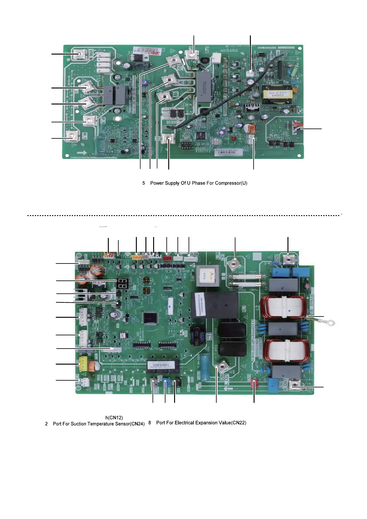
1 Reserved(CN2)
2 Input Port N For IPM Module(N)
4 Power Supply Of V Phase For Compressor(V)
3 Power Supply Of W Phase For
Compressor(W)
6 Output Port N Of PFC Module(N_1)
7 Output Port P Of PFC Module(P_1)
8 Input Port For PFC Inductance L_1(L_1)
9 Input Port For PFC Inductance L_2(L_2)
1 Port For Pressure Switc
3 Port For Pressure Sensor(CN28)
4 Port For Discharge Temperature
Sensor(CN8)
5 Port For Ambient Temperature And
Condenser Outlet Temperature
Sensor(CN9)
7 Reserved(CN30)
9 Input Port For Live Wire(CN1)
10 Input Port For Neutral Wire(CN2)
11 Output Port For Neutral Wire(CN3)
12 Ourput Port For Live Wire(CN4)
13 Reserved(CN7)
14 Port For 4-way Value(CN13)
15 Port For Eletric Heating Tape(CN14)
16 Input Port For Transformer(CN26)
10
20
19
18
25
17
16
23
22
21
11 13
9
8
7
6
1
9 10
2
345
10 Input Port N For PFC Module(VIN-N)
11 Input Port P For IPM Module(P)
12 Communicate Port Between PCB A
And PCB B(CN1)
13 +15V(CN6)
15 2614 13 12
17 Power Supply Port For Fan(CN18)
18 Port For Down Fan(CN19)
19 Port For Up Fan(CN17)
20 Output Port For Transformer(CN51)
21 Check Button(SW2)
22 Refrigerant Recovery Button
23 Digital Displays(DIS1)
24 Ground Wire(CN11)
25 Comunication Port For PCB A(CN6)
26 Power supply port for hydro-box
control board(CN16)
12
1
2
3 4 5 6 7 8
24
11
9.2.4 PCB for refrigerant system
PCB A, Inverter module for 1-phase 10~16kW unit
PCB B, Main control board for 1-phase 10~16kW unit

 Loading...
