The unit is only to be used in a closed water system.
Application in an open water circuit can lead to excessive
corrosion of the water piping.
When water is not moving inside the system in cold
weather, freezing is very likely and will damage
the system.
Checking the water circuit
The units are equipped with a water inlet and outlet for connection
to a water circuit. This circuit must be provided by a licensed technician
and must comply with local laws and regulations.
Checking the water volume and expansion vessel pre-pressure
The unit is equipped with a 5 L(for 5/7/9 kW unit, the volume is 2L)
expansion vessel that has a default pre-pressure of 1.5 bar.
To assure proper operation of the unit, the pre-pressure of the expansion
vessel might need to be adjusted and the minimum and maximum water
volume must be checked.
1. Check that the total water volume in the installation, excluding the
internal water volume of the unit, is at least 25L(for 5/7/9 kW unit,
the minimum volume is 15L) . Refer to 14 Technical specifications
to find the total internal water volume of the unit.
Before continuing installation of the unit, check the following:
■ The maximum water pressure = 3 bar.
■ The maximum water temperature is 70°C according to safety
device setting.
■ Always use materials that are compatible with the water used in the
system and with the materials used in the unit.
■ Ensure that components installed in the field piping can withstand
the water pressure and temperature.
■ Drain taps must be provided at all low points of the system to
permit complete drainage of the circuit during maintenance.
■ Air vents must be provided at all high points of the system. The
vents should be located at points that are easily accessible for
servicing. An automatic air purge is provided inside the unit. Check
that this air purge valve is not tightened too much so that automatic
release of air in the water circuit remains possible.
A
<A
9.3 Water pipework
All piping lengths and distances have been taken into consideration.
Requirements
Valve
The maximum allowed thermistor cable length is 20m.
This is the maximum allowable distance between the
domestic hot water tank and the unit (only for
installations with a domestic hot water tank).The
thermistor cable supplied with the domestic hot water
tank is 10m in length.
In order to optimize efficiency we recommend installing
the 3-way valve and the domestic hot water tank as
close as possible to the unit
Thermistor
cable
length
minus 2m
NOTE
■ In most applications this minimum water volume will be
satisfactory.
■ In critical processes or in rooms with a high heat load though,
extra water might be required.
■ When circulation in each space heating loop is controlled by
remotely controlled valves, it is important that this minimum
water volume is kept even if all the valves are closed.
NOTE
■ If the installation is equipped with a domestic hot water tank
(optional), please refer to the domestic hot water tank
Installation & Owner's Manual.
■ If there is no glycol (anti-freeze) in the system there is a power
supply or pump failure, drain the system (as shown in the figure
below).
26
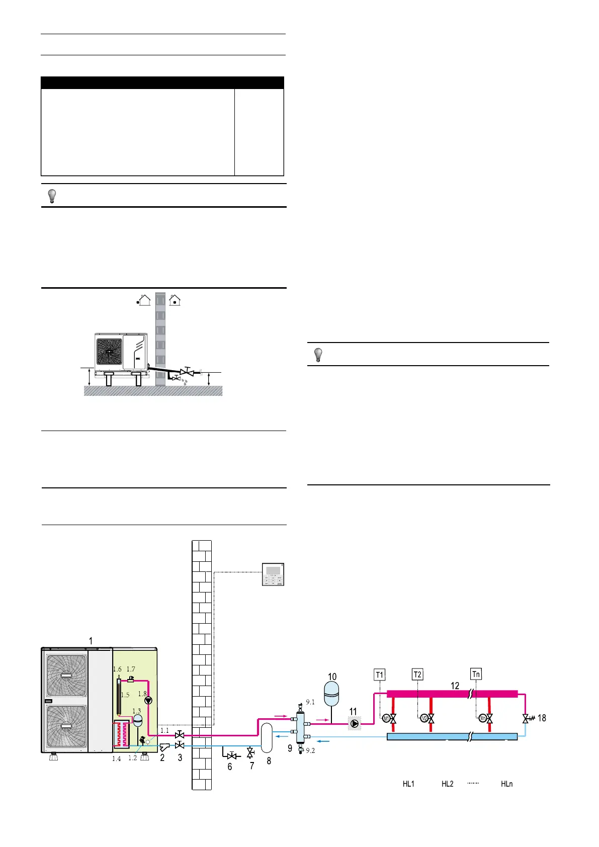
Example
1 Outdoor Unit
1.1 Manometer
1.2 Pressure Relief Valve
1.3 Expansion Vessel
1.4 Plate Heat Exchanger
1.5 Backup Heater
1.6 Air Purge Valve
1.7 Flow Switch
1.8 P_i: Circulation Pump Inside Unit
2 Y-shape Filter
3 Stop Valve (Field Supply)
4 User Interface
6 Drain Valve(Field Supply)
7 Fill Valve(Field Supply)
8 Buffer Tank(Field Supply)
9 Balance Tank(Field Supply)
9.1 Air Purge Valve
9.2 Drain Valve
10 Expansion Vessel (Field
Supply)
11 P_o: Outside Circulation Pump
(Field Supply)
12 Collector(Field Supply)
18 Bypass Valve(Field Supply)
Fhl 1...N Floor Heating Loop
M1...N Motorized Valve (Field
Supply)
T1…n Room Thermostat (Field
Supply)

 Loading...
