34
Procedure
1. Connect the cable to the appropriate terminals as shown in the
picture.
2. Fix the cable with cable ties to the cable tie mountings to ensure
stress relief
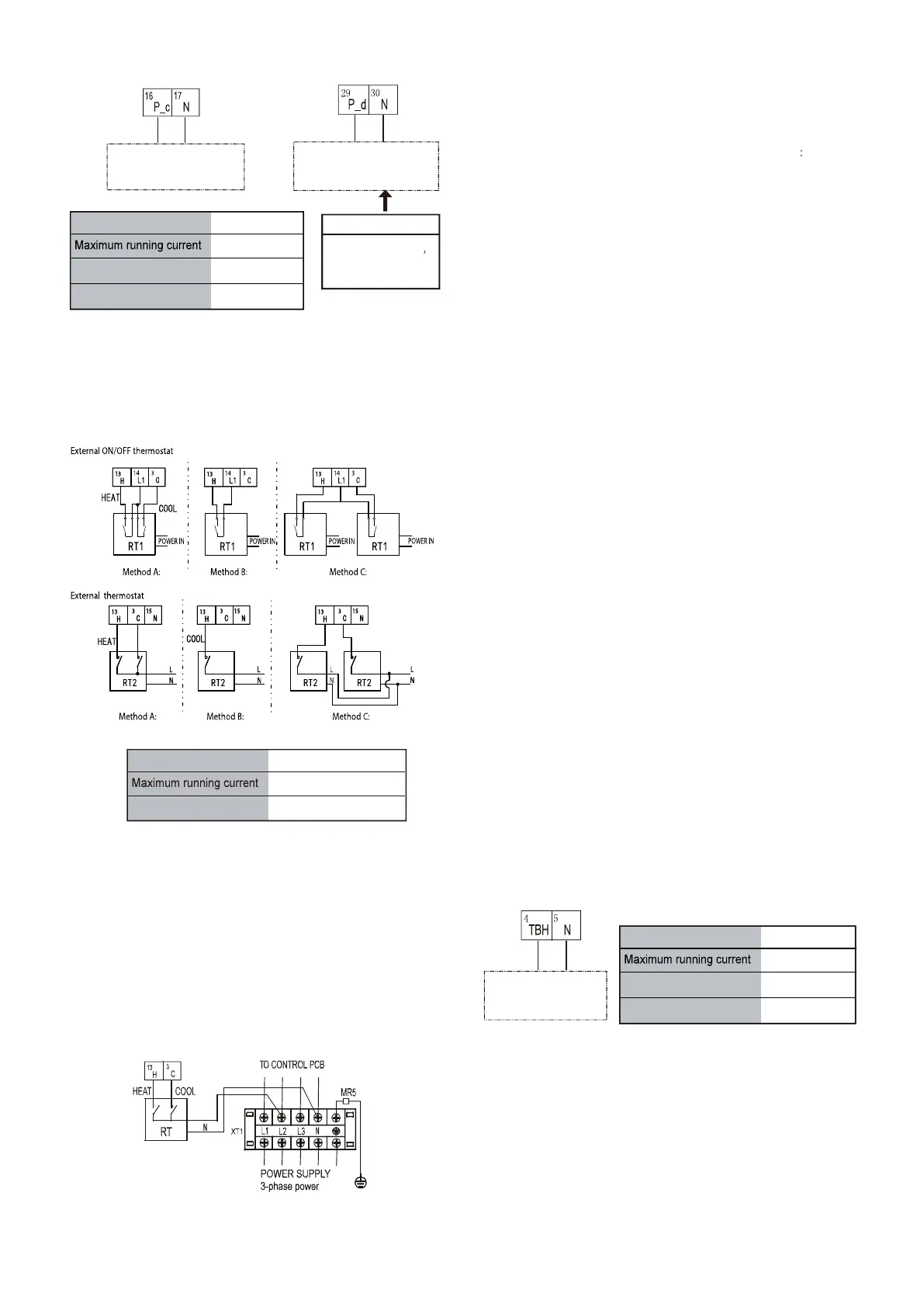
For room thermostat:
For booster heater:
For tank loop pump P_d and mix pump P_c:
Connection of the booster heater cable depends on the application.
Only when the domestic hot water tank is installed will this wiring be
needed. The unit only sends a turn on/off signal to the booster heater.
An additional circuit breaker is needed and a dedicated terminal is
needed to supply power to the booster heater.
See also "8 Typical application examples" and "10.7 Field
settings/DHW control” for more information.
PUMPC
CONTROL SIGNAL OUTPUT
PUMPD
CONTROL SIGNAL OUTPUT
TANK BOOST HEATER
CONTROL SIGNAL
OUTPUT
For 5/7/9 kW unit
the terminal number
is 37 and 38.
NOTE
0.2A
Wiring size
Voltage 220-240VAC
0.75mm
2
Note:
there are two optional connect method depend on the room
thermostat type.
1. Room thermostat type 1(RT1): “POWER IN” provide the working
voltage to the RT, doesn’t provide the voltage to the RT connector
directly. Port “14 L1” provide the 220V voltage to the RT connector.
Port “14 L1” connect from the unit main power supply port L of 1-
phase power supply, L2 port of 3-phase power supply.
Method A
RT can control heating and cooling individually, like the controller for
4-pipe FCU. When the hydraulic module is connected with the
external temperature controller, user interface FOR SERVICEMAN
set THERMOSTAT and ROOM MODE SETTING to YES
A.1 When unit detect voltage is 230VAC between C and N ,the unit
operates in the cooling mode
A.2 When unit detect voltage is 230VAC between H and N, the unit
operates in the heating mode.
A.3 When unit detect voltage is 0VAC for both side(L-N, H-N) the unit
stop working for space heating or cooling.
A.4 When unit detect voltage is 230VAC for both side(L-N, H-N) the
unit working in cooling mode.
Method B
RT provide the switch signal to unit. user interface FOR
SERVICEMAN set ROOM THERMOSTAT and MODE SETTING to
YES:
B.1 When unit detect voltage is 230VAC between H and N, unit turn
on.
B.2 When unit detect voltage is 0VAC between H and N, unit turn off.
Note:When ROOM THERMOSTAT is set to YES, the indoor
temperature sensor Ta can’t be set to valid, unit running only according
to T1.
Method C
Hydraulic module is connected with two external temperature
controllers, while user interface FOR SERVICEMAN set DUAL
ROOM THERMOSTAT to YES,
C.1 When unit detect voltage is 230VAC between H and N ,the MAIN
side turn on.When unit detect voltage is 0VAC between H and N, the
MAIN side turn off.
C.2 When unit detect voltage is 230VAC between C and N, the ROOM
side turn on according to climate temp curve. When unit detect voltage
is 0V between C and N), the ROOM side turn off.
C.3 When H-N and C-N are detected as 0VAC, unit turn off.
C.4 when H-N and C-N are detected as 230VAC, both MAIN and
ROOM side turn on.
Procedure
1. Connect the cable to the appropriate terminals as shown on the
picture
2. Fix the cable with cable ties to the cable tie mountings to ensure
stress relief
NOTE:
1.The wiring of the thermostat should correspond to the settings
of the user interface. Refer to 10.7 Field setting/Room Thermostat.
2. Power supply of machine and room thermostat must be
connected to the same Neutral Line and (L2) Phase Line(for 3-
phase unit only).
There are three methods for connecting the thermostat cable (as
described in the picture above) and it depends on the application.
2. Room thermostat type 2(RT2)(Recommend wire connection
method): L N provide the power supply to the RT connector directly.
L connect from the unit main power supply port L of 1-phase power
supply , L2 of 3-phase power supply.
Wiring size
Voltage
220~240VAC
0.2A
0.75mm
2
Type 2
Control port signal type
Wiring size
Voltage 220~240VAC
0.2A
0.75mm
2
Type 2
Control port signal type

 Loading...
