Do you have a question about the Midland Base Tech III and is the answer not in the manual?
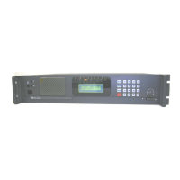
Details the LCD display layout, character capacity, and status indicators.
Explains the function of the five LEDs: DIGI, REP, ALM, TX, and BUSY.
Describes functions of keys without SHIFT, including number keys, A, B, C, D, *, #, CH, F(Scan), MON.
Details functions accessed via SHIFT key: 0-9, A-D, *, #, CH, F(Scan), MON.
Explains how to program the Base Tech III via PC, including data transfer modes.
Describes the procedure to recover the radio when programming software fails.
Details how to adjust volume level using the rotary knob, from VOLO to VOL-34.
Explains how to adjust squelch level using the rotary knob, from SQL-1 to SQL-15.
Describes adjusting LCD backlight level (DIM-0 to DIM-15) via the rotary knob.
Details selecting channels from 1 to 500 using CH and number keys.
Explains P-25 squelch modes: Normal SQ and Selective SQ.
Describes selecting PTT mode for analog or digital transmission.
Explains P-25 calling modes: Group Call (GP), All Call (AL), and Individual Call (ID).
Details setting up individual calls using target numbers or IDs.
Shows how group names (max 8 characters) are indicated for TGID.
Explains how to lock/unlock keys using SHIFT+8, and its limitations.
Details how to check Rx/Tx width, base mode, and CTCSS/DCS status.
Shows how to view P-25 status: Unit ID, RX NAC, TX-NAC, and TGID.
Explains how to display frequencies, band type, and mode using SHIFT+CH.
Describes how to enable/disable LCD backlight hold using SHIFT+1.
Explains how to select High/Low TX power using SHIFT+2.
Details how the radio displays caller's Unit ID or Individual ID.
Describes how the radio indicates emergency calls and displays caller ID.
Explains automatic repeater functionality for digital and mixed modes.
Details how to control the radio remotely via EXT/CH signals, max 16 channels.
Covers various P-25 transmitter test patterns: test, symbol rate, low deviation, C4FM, tone.
Details adjustable parameters like RX 0dbm Out, RX FX828 MOD-1, TX DIGITAL DEVI, TX ANALOG DEVI.
Explains how to enter Key Test mode and test individual keys and rotary switches.
Shows how to view firmware and DSP software versions on startup.
Details how to display the radio's serial number using key presses on startup.
Explains how to display the programming software version via key press on startup.
Describes the self-diagnostic function that checks EEROM data on startup.
Explains error indicators (ALM LED) for faulty units like RX PLL, TX PLL, or PA.
Describes automatic main CPU restart upon detecting internal firmware malfunctions.
Lists common RS232 communication error messages shown on the LCD.
Details LCD messages for DSP issues: Failure, Not Ready, Serial Error.
| Brand | Midland |
|---|---|
| Model | Base Tech III |
| Category | Accessories |
| Language | English |