Base Tech III Operating Manual
2
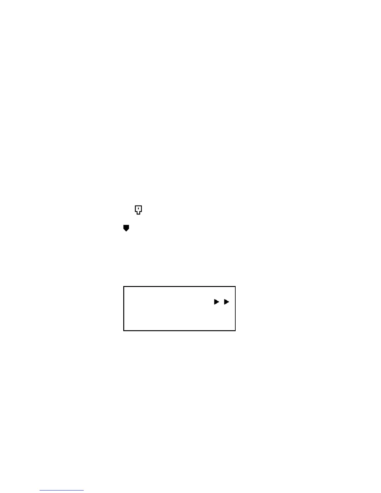
1) LCD Display
LCD display consists of 4 x 20 characters as shown.
Line 1 : Incoming RSSI with 10 steps
Line 2: Output power levels with 10 steps
Line 3: Left 4 letters show Channel Numbers. Middle 8 letters
show channel name (if not programmed, shows blank).
Right 4 letters show status of the radio.
1/ RX mode : M= Mix, both analog and digital can be received
D= Only digital can be received.
2/ TX mode: D=PTT digital transmission
A=PTT analog transmission
3/ Monitor mode: X= Monitor off
S= Selective squelch
4/ P-25 squelch: N= Normal squelch
S= Selective squelch
5/ Key lock mode: =Key lock
6/ Shift mode: Depressing the SHIFT KEY (back to normal
after 2 seconds)
Line 4 : Left 2 letters .show GROUP CALL, ALL CALL, INDIVIDUAL CALL.
Right 18 letters show GROUP NAME, INDIVIDUAL NUMBERS, ETC.
1 2 3 4 5 6 7 8 9 0 1 2 3 4 5 6 7 8 9 0
1
2
3
4
RX = = = = = = = = = =
TX = = = = = = = = = =
C001 Channel MDXN
GP 500
2) LED Display
BASE TECH III has 5 LED's, from the left ;
DIGI= LED on when receiving digital signal
REP= LED on when repeat mode. BASE TECH III can be programmed
SIMPLEX -SEMIDUPLEX - DUPLEX- REPEATER on a per channel basis
ALM= LED flashing on when an error on either TX or RX occurs
TX= LED on when in Transmit
BUSY= LED on when carrier is present