en - English
37
Payment system in programme operation
The wiring diagram is provided at the end
of these operating and installation instruc-
tions in section (“Programme opera-
tion”).
- C4030, C4031, C4060, C4065, C4070,
C4080
- C5002, C5004
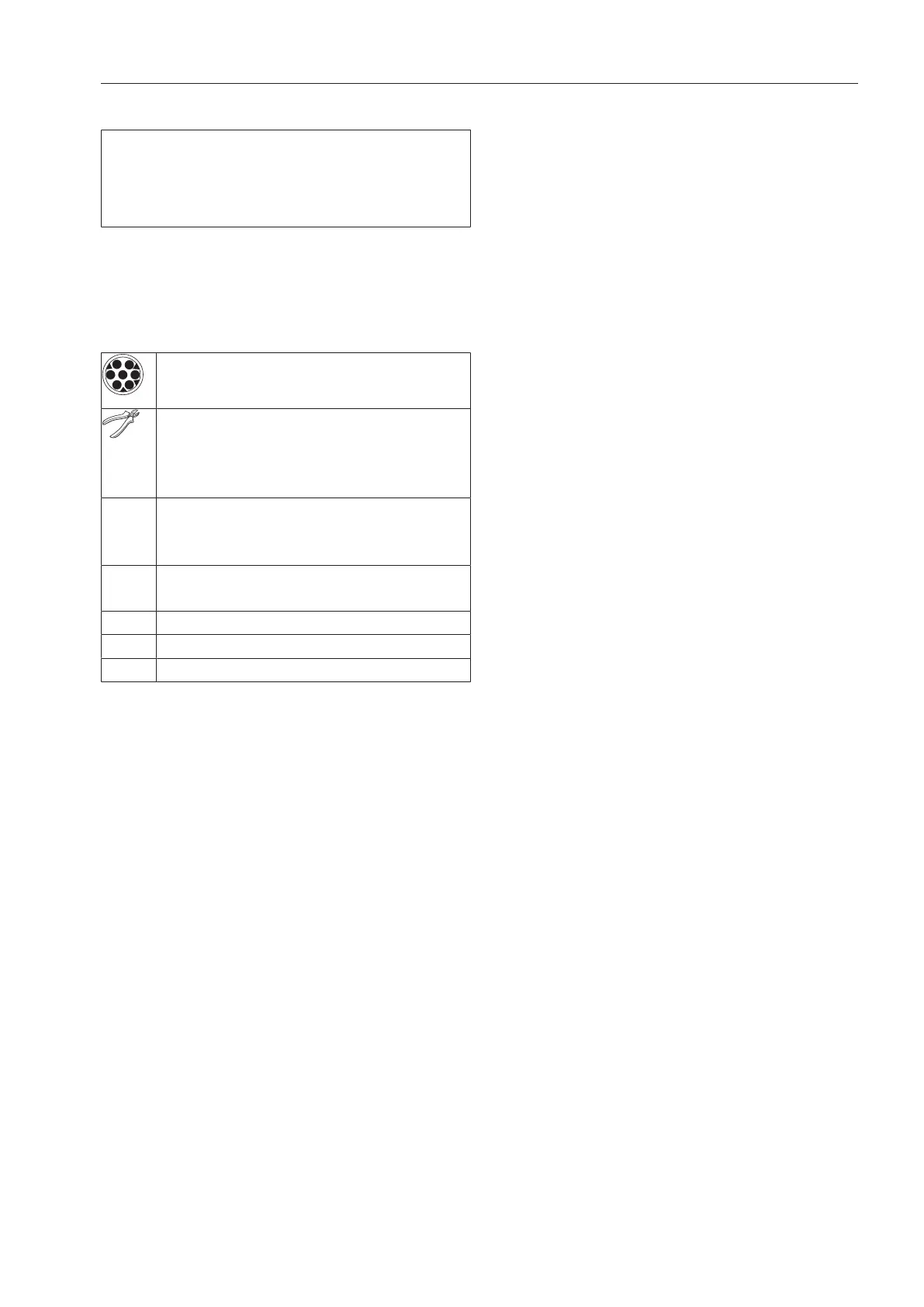
Legend
7-pin coupling of the payment sys-
tem
The 7-pin coupling of the payment
system can be removed to connect
the cables directly with the Con-
nector Box box terminals.
Con-
necto
r Box
Terminal sockets of the Connector
Box box
C Schematic diagram of the electrical
circuit in the payment system
Timed operation
Programme operation
Symbol for PE terminal (earth)
 Loading...