en - English
38
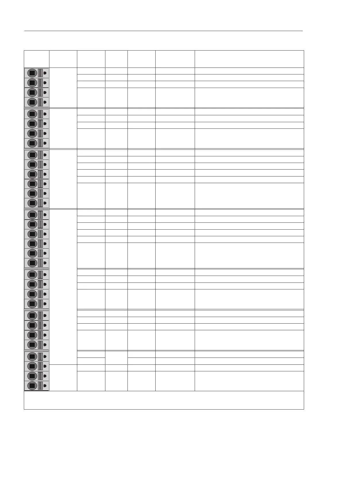
Current carrying capacity table
App
lication
Terminal
assign
ment
Signal
Signal
direction
Current
carrying
capacity
Description
PE Protective earth
PE Protective earth
PE Protective earth
PE Protective earth
Peak load
(DIN 18875)
1.1 L' aSwitch-on signal
1.2 L' bHeating demand
1.3 L' cHeating enable
1.4 N' dNeutral conductor
Payment system
2.1 L' Appliance ready for operation
2.2 L' Programme status
2.3 L' Programme buying impulse
2.4 N' Time buying signal
2.5 N' Power supply
2.6 L Power supply
PWM (washing machine): dispensing
PDR (dryer): additional components
3.1 N' 1.0A Ext. power supply
3.2 L 1.0A Ext. power supply
3.3 L' 4.0A Dispensing 1/Additional fan
3.4 N' 4.0A Power supply
3.5 L' 1.0A Dispensing 2/Exhaust valve
3.6 N' 1.0A Power supply
3.7 L' 1.0A Dispensing 3/Indicator light/Buzzer
3.8 N' 1.0A Power supply
3.9 L' 1.0A Dispensing 4
3.10 N' 1.0A Power supply
3.11 L' 1.0A Dispensing 5
3.12 N' 1.0A Power supply
3.13 L' 1.0A Dispensing 6
3.14 N' 1.0A Power supply
4.1
+13V
Empty sensor*
4.2 Empty sensor*
5.1 Coding
5.2 Coding
L' = switched phase, N' = switched neutral conductor
* see section “Current carrying capacity of the inputs and outputs”
Total current load of electronic module: see section “Installation”.
 Loading...