TM-716 Page 11MSW And LMSW Series
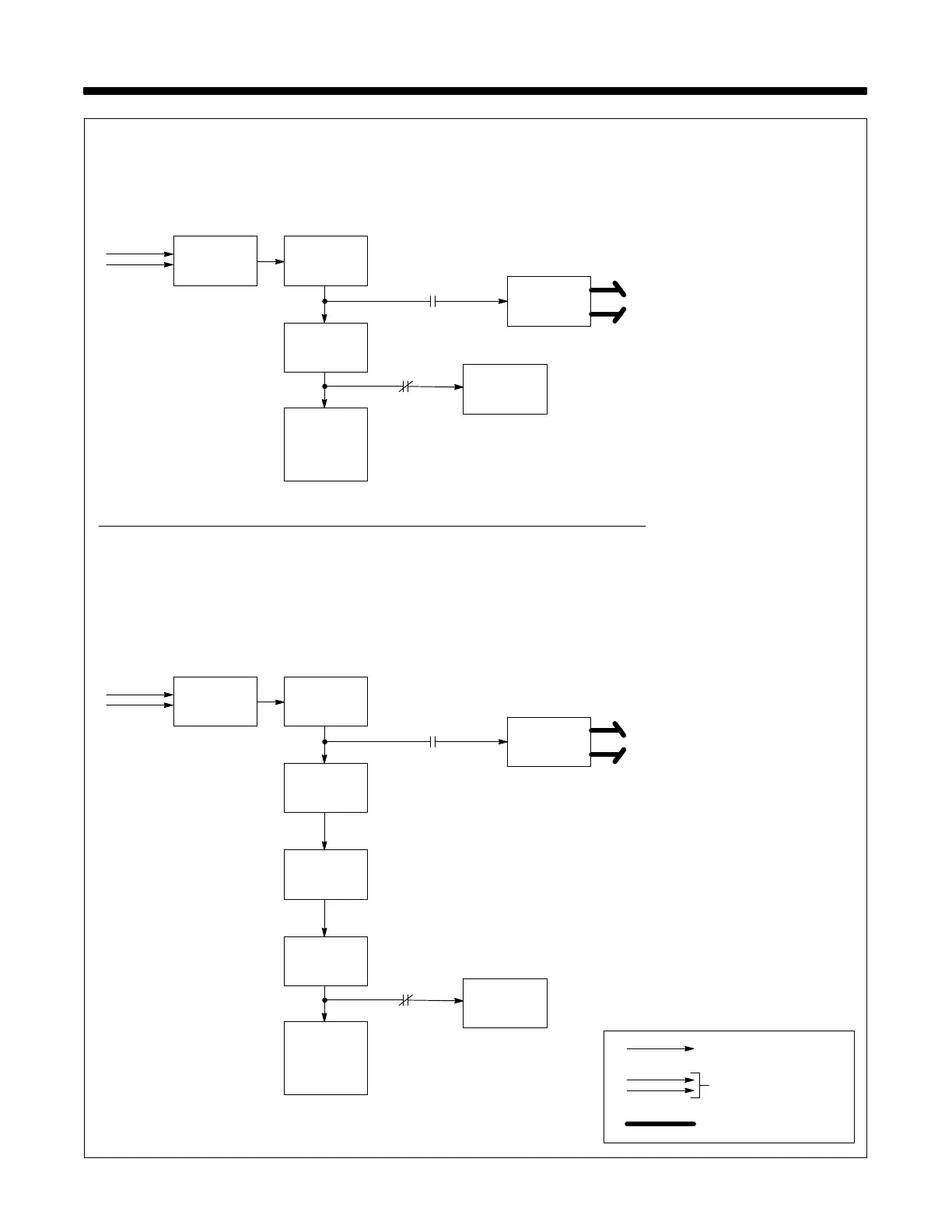
SECTION 5 − THEORY OF OPERATION
Main
Transformer
T1
8
1 Input Power Plug PLG1
Provides connection for line input
power.
2 Power Switch S1
Turns unit On/Off.
3 Control Transformer T2
(220 V Models)
Supplies power to spot timer control
circuit.
4 Fuse F1 (220 V Models)
Provides overload protection for
T2.
5 Start Switch PB1
Turns weld current On/Off.
6 Spot Weld Delay Timer TD1
And Pilot Light PL1
TD1 provides 0 to 5 seconds of
weld time.
PL1 turns on when weld cycle be-
gins and turns off when weld cycle
ends.
7 Contactor W
Connects line input power to main
transformer T1.
8 Main Transformer T1
Supplies power to weld output cir-
cuit. The transformer steps up the
current and steps down the voltage.
Resistance spot welds are made
with very low voltage (1-3 volts)
and with very high current
(4000-5000 amperes) applied un-
der pressure for a brief time period
(1-3 seconds) which causes in-
tense localized heating and a weld.
Weld Current Circuit
AC Control Circuits
1 Power
Single-Phase
Line Input
Power
Input
1
Power
Plug PLG1
Power
2
Switch
S1
Start
5
Switch
PB1
6
Contactor
7
W
TD1
110 Volts Model With A Timer
Single-Phase
Line Input
Power
Input
1
Power
Plug PLG1
Power
2
Switch
S1
Control
3
Fuse
4
Transformer
T2
F1
W
220 Volts Models With A Timer
Spot Weld
Delay Timer
TD1 And
Pilot Light
PL1
Main
Transformer
T1
8
W
Start
5
Switch
PB1
6
Contactor
7
TD1
W
Spot Weld
Delay Timer
TD1 And
Pilot Light
PL1




 To Next Page