OM-2228 Page 14
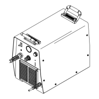
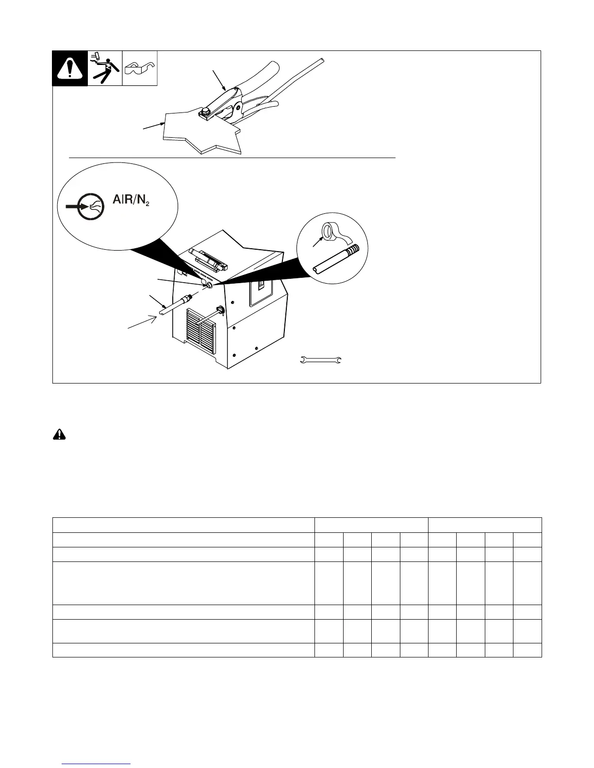
4-6. Connecting Work Clamp and Gas/Air Supply
1 Work Clamp
2 Workpiece
Connect work clamp to a clean,
paint-free location on workpiece, as
close to cutting area as possible.
. Use only clean, dry air with 90
to 120 psi (620 to 827 kPa)
pressure.
3 Gas/Air Inlet Opening
4 Hose
. Hose must have a minimum
inside diameter of 3/8 in.
(9.5 mm).
5 Teflon Tape
Obtain hose with 1/4 NPT right-
hand thread fitting. Wrap threads
with teflon tape (optional) or apply
pipe sealant, and install fitting in
opening. Route hose to gas/air
supply.
Adjust gas/air pressure according
to Section 5-2.
Tools Needed:
5/8, 1-1/8 in.
3
4
Ref. 803 640-A / Ref. 192 441 / Ref. 802 185-B
Rear of Unit
5
1
2
From
Gas/Air
Supply
90−120 psi
4-7. Electrical Service Guide
Failure to follow these electrical service guide recommendations could create an electric shock or fire hazard. These recommenda-
tions are for a dedicated branch circuit sized for the rated output and duty cycle of the welding power source.
NOTICE − Actual input voltage should not be 10% less than minimum and/or 10% more than maximum input voltages listed in table. If actual input
voltage is outside this range, output may not be be available.
. For any single or three phase voltage from 208 V to 575 V, the Amperes Input at Rated Load Output is the same for 50 Hertz or 60 Hertz input
power. For example, the amperes input for 230 V, 50 Hz, single-phase input power is 33 amperes. The amperes input for 230 V, 60 Hz, single-phase
input power is also 33 amperes.
60 Hz Models
Single Phase Three Phase
Input Voltage (V) 208 230 460 575 208 230 460 575
Input Amperes (A) At Rated Output 36 33 16 13 21 20 9 8
Max Recommended Standard Fuse Rating In Amperes
1
Time-Delay Fuses
2
45 40 20 15 25 20 10 10
Normal Operating Fuses
3
50 50 25 20 30 30 15 10
Min Input Conductor Size In AWG
4
10 10 14 14 12 14 14 14
Max Recommended Input Conductor Length In Feet (Meters)
72
(22)
89
(27)
138
(42)
215
(66)
87
(27)
69
(21)
275
(84)
429
(131)
Min Grounding Conductor Size In AWG
4
10 10 14 14 12 14 14 14
Reference: 2008 National Electrical Code (NEC) (including article 630)
1 If a circuit breaker is used in place of a fuse, choose a circuit breaker with time-current curves comparable to the recommended fuse.
2 “Time-Delay” fuses are UL class “RK5” . See UL 248.
3 “Normal Operating” (general purpose - no intentional delay) fuses are UL class “K5” (up to and including 60 amps), and UL class “H” ( 65 amps and
above).
4 Conductor data in this section specifies conductor size (excluding flexible cord or cable) between the panelboard and the equipment per NEC Table
310.16. If a flexible cord or cable is used, minimum conductor size may increase. See NEC Table 400.5(A) for flexible cord and cable requirements.

 Loading...