CHAPTER 7 – 7200 CNC OPERATION
7 The Function Keys
Highlighted Function Keys are active or available.
8 Status Window
Status Window displays detailed information on the state of the control. A
detailed description is given below.
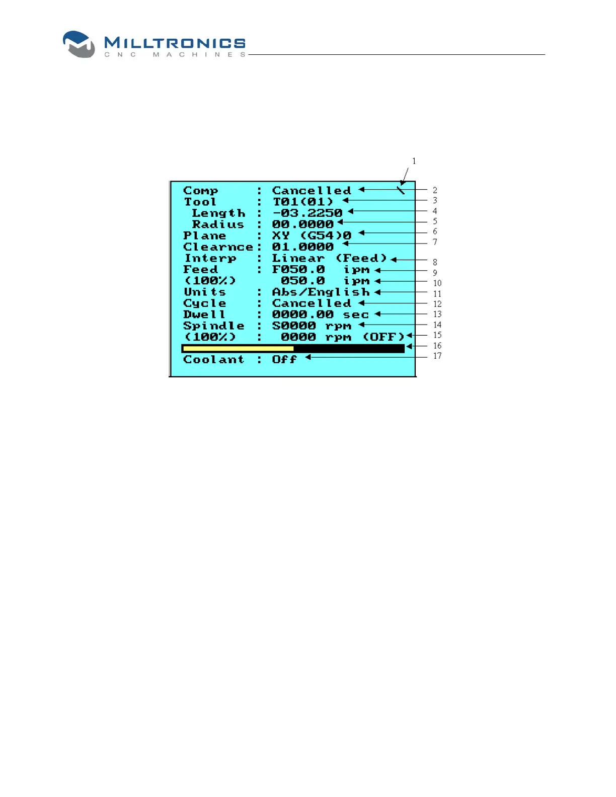
Diagram of Status Window
1 The \ changes back and forth to / and \ each time the status window is updated.
2 Comp: Tool Radius Compensation (Left, Right or Cancelled)
3 Tool: The first two digits indicate the active tool number. The second two digits in
parentheses indicate the pending tool number. If you execute a T14 without the
M6 the pending tool number will be 14.
4 The tool length.
5 The tool radius.
6 Plane and work offset: The plane is XY (G17), ZX (G18), or YZ (G19). The work
offset shows the current work offset G54 (0)…G59 (9).
7 Clearance or R-Plane.
8 Interpolation, Linear (Feed), Linear (Rapid), Circular (CW), or Circular (CCW)
9 Feedrate: The programmed feedrate and its units (English feed per minute) ipm,
(Metric feed per minute) mmpm, (English feed per revolution) ipr, (Metric feed per
revolution) mmpr or (inverse feed) /min or /sec (If the machine is rapid mode the
units will always be ipm or mmpm.)
10 Feedrate override: The position of the feedrate override and the resulting
feedrate. If the machine is programmed to move faster than its maximum, the
clamped feedrate will be displayed, and an “*” will be displayed next to the %.
11 Units: (Absolute) Abs or (Incremental) Inc and English or Metric
12 Cycle: If there is a canned cycle or autoroutine active it will be displayed on this
line.
13 Dwell: When a dwell is executed the dwell time will count down to zero.
14 Spindle: The programmed revolutions per minute.
55