iv
Pellerin Milnor Corporation
Figure 4 Examples of Manifolds for Chemical Tubes. Your equipment can look
different.......................................................................................................................9
Figure 5 A Configuration that Prevents Flow in the Machine When the Pump is
Off (if the chemical tube and tank have no pressure) ...............................................10
Figure 6 Pump Signal Connections.........................................................................................13
Figure 7 Timer Stop Connections ..........................................................................................14
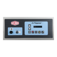
Figure 8 E-P Express
®
Control Panel......................................................................................15
Figure 9 Location of DIP Switches .......................................................................................19
Figure 10 Controls Identification on Serial Memory Storage Device ......................................38
Figure 11 Processor Board ........................................................................................................56
Figure 12 Serial Memory Storage Device.................................................................................62
Figure 13 Rear View of Circuit Board ......................................................................................62
Figure 14 9-Pin DIN Connector Pin Identification (from wire entry side of
connectors)................................................................................................................64
Figure 15 Wiring Diagram for Cable to Connect Two or More Machines ...............................66
Figure 16 Wiring Diagram for Cable to Connect a Machine to a Serial Memory
Storage Device..........................................................................................................67
Tables
Table 1 Trademarks ................................................................................................................2
Table 2 How to Read and Change Data ..................................................................................4
Table 3 Chemical Injection Signals ......................................................................................12
Table 4 DIP Switch Settings for Industry Configurations ....................................................20
Table 5 Summary of Step Types ...........................................................................................28
Table 6 Chemical Signals and Supplies ................................................................................30
Table 7 Controllers Capable of Transferring Memory .........................................................36
Table 8 E-P Express
®
Inputs .................................................................................................54
Table 9 E-P Express
®
Outputs ..............................................................................................55
Table 10 Interpretation of Test DIP Switch Display ...............................................................57
Table 11 DIP Switch Positions for E-P Plus
®
and E-P Express
®
Machines (External
transmit button required) .........................................................................................63
Table 12 External Serial Link Pin Assignments .....................................................................64
Table 13 Milnor Printer Cables ...............................................................................................67
Table 14 Required Settings for Citizen GSX-190 Printer ......................................................68
Table 15 Required Settings for Epson LX300 Printer ............................................................68
Contents