— 1.11 —
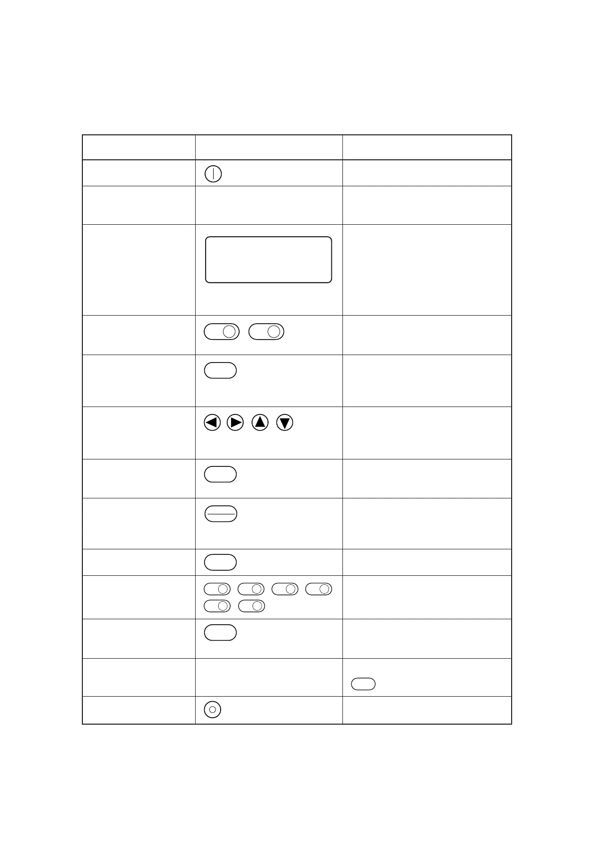
Name Representation Function
1 POWER ON switch Used to turn ON the power to the device.
2 POWER lamp Lights up (in green) when the power to the
device is turned on.
3 LCD LCD indicates states of the device and
specified menus on its 16-column and
4-line cells.
In the case where an indication on LCD is
referred to in the text, it is shown with
bracketed as [TOOL SELECT].
4 PAGE key , Used to advance or return the page on the
LCD.
5 CE key Used to cancel the performance (data clear,
copy, etc.) or return to the previous
hierarchy without entering an input value.
6 JOG key , , , Used to scroll the head in the direction of
the arrow while local menus (see pages 2.2
to 2.5) are displayed.
7 ORIGIN key Used to set a plotting origin (ORIGIN) at
the top of the cutting area of the device.
8 REMOTE/LOCAL Used to change over the operation mode
key of the device between the remote and the
local modes.
9 END key Used to enter an input value.
10 FUNCTION key , , , , Used to select a function from the local
, menu and input a set value.
11 VACUUM key Used to turn on/off the blower for
pneumatically picking a work.
12 VACUUM lamp Lights up (in green) when pressing the
VACUUM
key to actuate the blower.
13 POWER OFF switch Used to turn of the power to the device.
[ LOCAL ] 1 / 4
TOOL SELECT ———>
CONDITION ———>
TEST CUT ———>
PAGE
+
PAGE
_
C E
ORIGIN
REMOTE
LOCAL
END
F1
+
F1
_
F2
+
F2
_
F3
+
F3
_
VACUUM
 Loading...


