Do you have a question about the MIMAKI CG-60SL and is the answer not in the manual?
Lists and describes all items supplied with the plotter for verification.
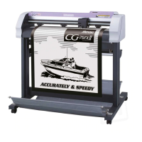
Explains the main parts and their functions on the front and rear of the plotter.
Details the display panel, buttons, and key functions for controlling the plotter.
Instructions for connecting USB and power cables to the plotter and host computer.
Describes the four operating modes of the plotter: NOT-READY, LOCAL, REMOTE, and FUNCTION.
Outlines the sequential steps for operating the plotter, from tool installation to power off.
Step-by-step guide on how to install cutters and pens into the plotter's tool holder.
Procedure for safely powering on the plotter and checking its initial status.
Explains how to adjust parameters like speed, pressure, and offset for different cutting tools.
Instructions for correctly loading both cut sheets and roll sheets onto the plotter.
How to perform a test cut to verify tool conditions and ensure proper cutting quality.
Steps for initiating the cutting or plotting process after setting the origin and conditions.
Procedure for safely shutting down the plotter after operation is complete.
How to use jog keys for precise positioning, setting origins, and defining cutting areas.
Compensates for variations in cut length due to sheet thickness or roller differences.
Enables repeating a cut job multiple times or setting intervals between cuts.
Reduces non-plotting areas to maximize the usable cutting or plotting space.
Allows rotation of the coordinate system and origin to change cutting direction.
Divides large data into smaller sections that fit within the sheet width for cutting.
Sorts cutting data to optimize the cutting sequence or perform specific cutting patterns.
Manually feeds the sheet for checking alignment or preparing for long data cuts.
Temporarily pauses cutting to fix sheet misalignment without losing the cutting position.
Aborts the current cutting job and clears data from the receiver buffer.
Executes pre-stored sample cuts to diagnose cutting errors or verify plotter settings.
Prints or transmits the current plotter settings for reference or troubleshooting.
Dumps received data in ASCII format for debugging or analysis of communication.
Assigns unique device numbers to plotters when connected via USB to a single computer.
Creates dashed or perforated cut lines by adjusting half-cut pressure and length.
Uses a pouncing pin to create perforated lines for marking or guiding construction.
Allows selection of the user interface language from a list of supported languages.
Provides access to various customizable settings for optimizing plotter operation.
Restores all plotter settings and parameters to their factory default values.
Offers remedies for common operational problems based on phenomenon, cause, and solution.
Lists specific error codes, their causes, and recommended solutions for display errors.
Explains non-error messages that indicate plotter status or require user action.
Lists detailed technical specifications, including dimensions, speed, power, and material compatibility.
Instructions for replacing and adjusting the plotter's cutter blade for optimal performance.
A template for recording sheet names and distance correction values for reference.
Visual diagrams illustrating the sequence of key presses for various plotter functions.
| Type | Cutting Plotter |
|---|---|
| Cutting Method | Drag Knife |
| Maximum Media Thickness | 0.25 mm |
| Blade Type | Standard Blade |
| Interface | USB 2.0 |
| Power Requirements | 50/60 Hz |
| Weight | 25 kg |
| Maximum Cutting Speed | 500 mm/s |
| Cutting Force | 20 – 250 g |
| Power Supply | AC 100-240 V |
| Operating Temperature | 5 – 35 °C |
| Operating Humidity | 35-80% RH (non-condensing) |
| Dimensions (W x D x H) | 950 mm x 430 mm x 330 mm (37.4 in x 16.9 in x 13.0 in) |