© 2009 MIMAKI ENGINEERING CO.,LTD.
6.2.2 P.1
1
2
3
4
5
6
7
8
R.1.0
Maintenance Manual > Disassembly and Reassembly > Ink-related Parts > Removing of Head Unit
Model CJV30/TPC Issued 2008.08.04 Revised F/W ver. 1.00 Remark
1.0
6.2.2 Removing of Head Unit
Work procedures
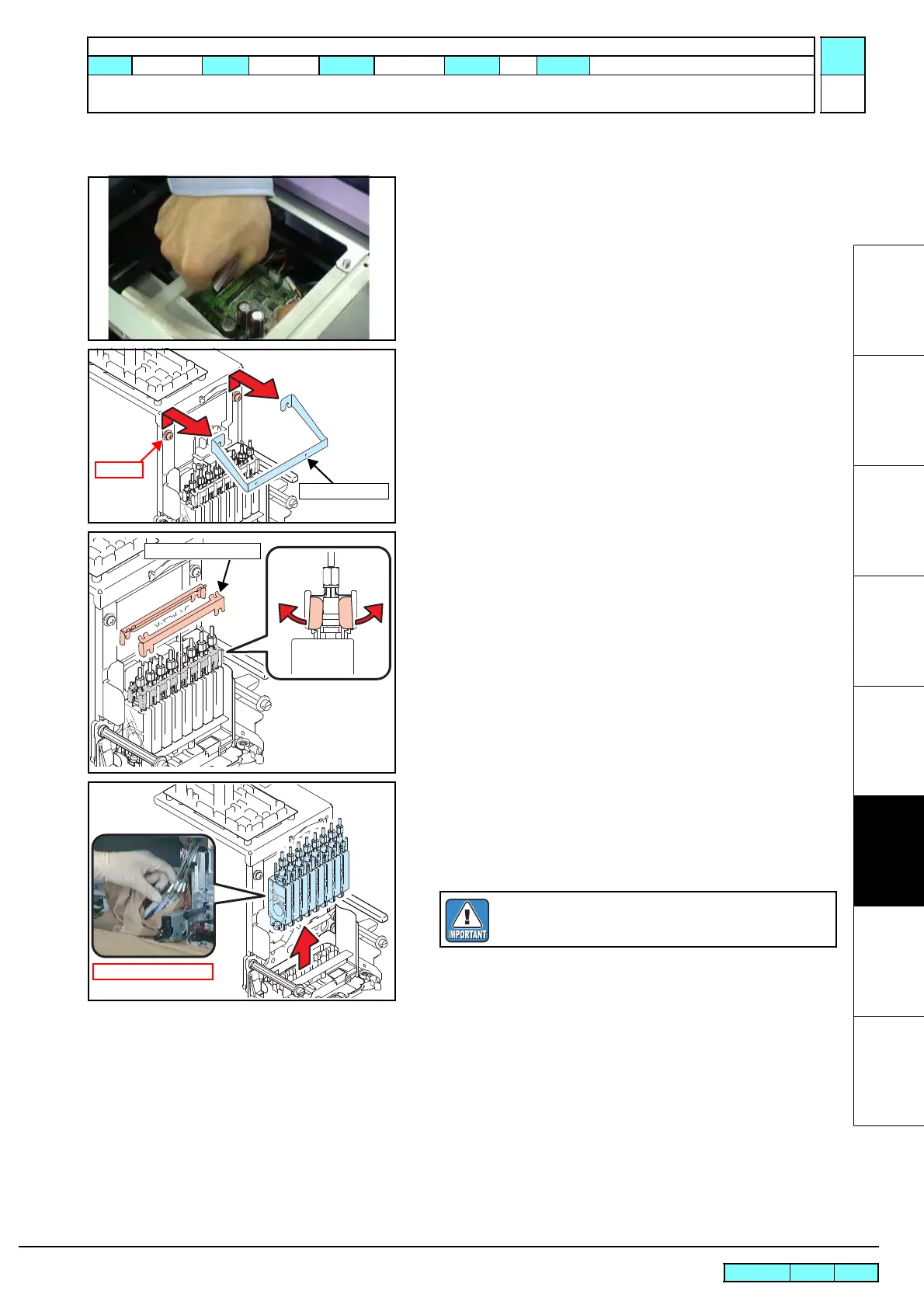
1. Pull out the head FFC assy and head memory cable assy from
the ink slider PCB assy through the top where the wiring cover
removed.
2. Move the print head carriage onto the platen to make your work
easy.
3. Loosen the screws at two locations on the right and left to
remove the P cover BKT.
4. Remove damper lock SPs.
Near side: Rotate right and left edges towards you and
remove them.
Rear side: Rotate right and left edges to the rear and remove
them.
5. Place the waste cloth around the head unit so as not to
contaminate the platen.
6. Pull out all pressure damper SP assys from the print head
carriage and wrap them with the waste cloth so as not to
contaminate their surroundings.
Do not touch the film of the damper assy.

 Loading...


